Low-cost automatic charging and discharging control circuit and control method for storage batteries

A charge-discharge control and storage battery technology, which is applied to battery circuit devices, electric vehicles, circuit devices, etc., can solve the problems of inability to switch between external charging power sources and batteries accurately, affect the service life of electrical devices, and burn out electrical devices. It is conducive to wide application, less components and lower cost

Pending Publication Date: 2019-07-09
BEIDOU AEROSPACE AUTOMOBILE BEIJING CO LTD
View PDF0 Cites 0 Cited by
  • Summary
  • Abstract
  • Description
  • Claims
  • Application Information

AI Technical Summary

Problems solved by technology

This solution has extremely high requirements on the accuracy of AD acquisition. Due to the inevitable existence of errors and the various load conditions of the circuit, this solution is unstable, and it is easy to cause the control pin not to be turned on at the moment of power failure, resulting in a gap between the external charging power supply and the battery. Can't switch accurately
Since the voltage of the external charging power source is often higher than the external working voltage of the battery, if the switching is not timely or the switching fails, the external charging power supply will always supply power to the electrical devices, making the electrical devices in an overvoltage state for a long time, and there will be The risk of burning electrical components affects the service life of electrical components

Method used


Image

  • Low-cost automatic charging and discharging control circuit and control method for storage batteries
  • Low-cost automatic charging and discharging control circuit and control method for storage batteries
  • Low-cost automatic charging and discharging control circuit and control method for storage batteries

Examples


Embodiment Construction

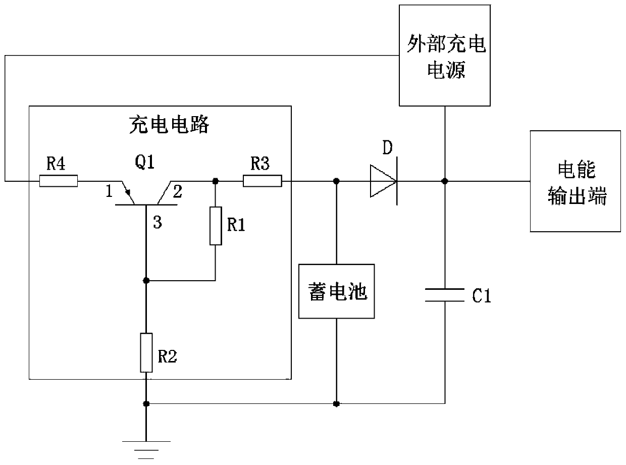
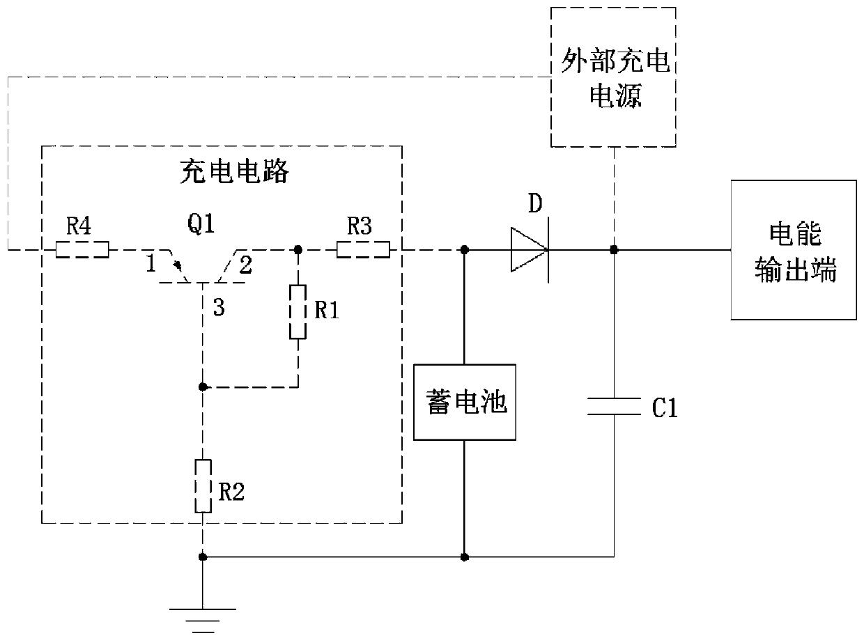
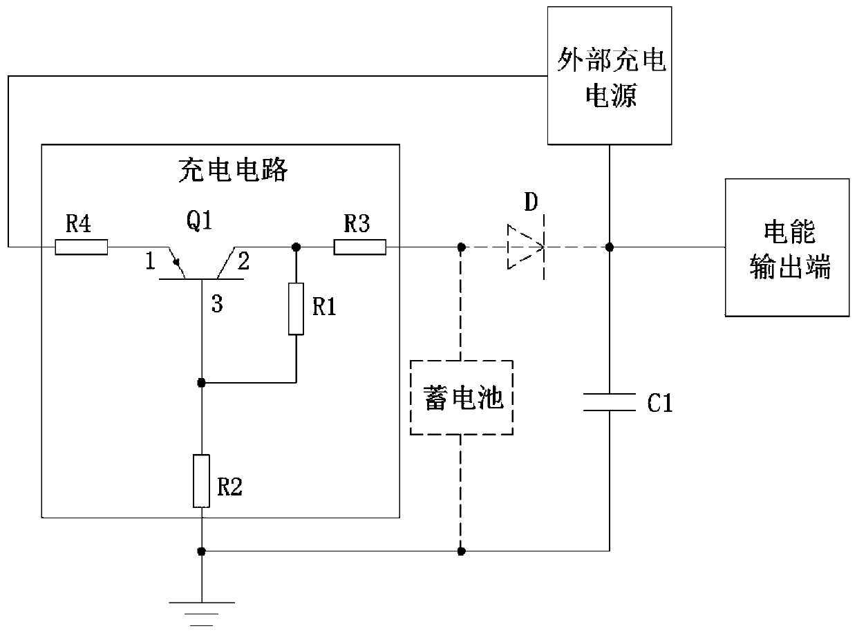
[0024] The technical solutions of the present invention will be clearly and completely described below in conjunction with the accompanying drawings. Apparently, the described embodiments are some of the embodiments of the present invention, but not all of them. Based on the embodiments of the present invention, all other embodiments obtained by persons of ordinary skill in the art without making creative efforts belong to the protection scope of the present invention.

[0025] In the description of the present invention, it should be noted that the terms "center", "upper", "lower", "left", "right", "vertical", "horizontal", "inner", "outer" etc. The indicated orientation or positional relationship is based on the orientation or positional relationship shown in the drawings, and is only for the convenience of describing the present invention and simplifying the description, rather than indicating or implying that the referred device or element must have a specific orientation, ...


PUM


Abstract

The invention relates to the technical field of storage battery charging and discharging control, in particular to a low-cost automatic charging and discharging control circuit and control method forstorage batteries. The low-cost automatic charging and discharging control circuit comprises a charging circuit of which one end is electrically connected with an external charging power supply and the other end is electrically connected with the conducting end of a diode. The cut-off end of the diode is electrically connected with the external charging power supply and a power output terminal. The low-cost automatic charging and discharging control circuit further comprises a storage battery of which one end is electrically connected with the conducting end of the diode and the other end is grounded. According to the low-cost automatic charging and discharging control circuit and control method for storage batteries disclosed by the invention, the automatic charging and discharging function of the storage battery is realized by making use of the switching characteristics of the diode, and there is no need for enabling control by an external controller. The circuit is simple, and the system instability of charging-discharging switching of the storage battery is overcome. The circuit has fewer components and occupies less PCB area, which is conducive to miniaturization and light weight. Moreover, the cost is greatly reduced, which is conducive to wide application.

Description

technical field [0001] The invention relates to the technical field of storage battery charging and discharging control, in particular to a low-cost automatic charging and discharging control circuit and control method for storage batteries. Background technique [0002] There are mainly two schemes for the existing storage battery charge and discharge control: one is to use a power management chip. The cost of this solution is high, and it needs to occupy the I / O port or bus of the MCU (vehicle controller), and the switching of charging and discharging of the battery needs to be actively controlled, so more peripheral circuits are required. The other is that the MCU controls the triode to enable charge and discharge management. In this solution, 5V direct charge is used for charging; when discharging, AD acquisition voltage is required to cooperate with charge and discharge management. When the voltage is lower than the threshold value, the enable is turned on to charge the...

Claims


Application Information

Patent Timeline
IPC IPC(8): H02J7/00
CPCH02J7/0068
Inventor 刘贵生张鑫刘志钢
Owner BEIDOU AEROSPACE AUTOMOBILE BEIJING CO LTD
Why Eureka
Try Eureka