Stator core, stator comprising stator core and preparation method of stator
A stator iron core and iron core technology, which is applied in the manufacture of stator/rotor body, motor generator, magnetic circuit shape/style/structure, etc., can solve the problems of low production efficiency, high labor intensity and low material utilization rate. , to achieve the effect of improving production efficiency, liberating labor, and simple operation
- Summary
- Abstract
- Description
- Claims
- Application Information
AI Technical Summary
Problems solved by technology
Method used
Image

Examples
Embodiment Construction
[0047] Preferred embodiments of the present invention will be described in detail below in conjunction with the accompanying drawings.
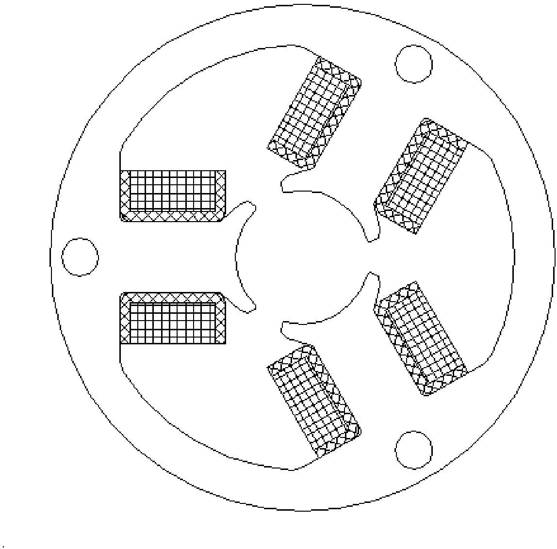
[0048] In order to achieve the purpose of the present invention, in some embodiments of the open slot stator core, the stator including the stator core and the manufacturing method thereof, the open slot stator core includes: three core units 1, and the stator core passes through three A core unit 1 is spliced and enclosed along its circumference; as Figure 5 As shown, each core unit 1 includes: a yoke 11 and a tooth 12 extending toward the axis of the stator core on the yoke 11; a splicing protrusion 2 for splicing is provided on the yoke 11 and is used for splicing The protrusion 2 matches the splicing groove 3; the width of the tooth part 12 is equal inside and outside, and forms an open groove structure after splicing with other core units.
[0049] The yoke portion 11 includes: a positioning portion 111 and splicing portions 112 arra...
PUM
 Abstract
Description
Claims
Application Information
 - Generate Ideas
- Intellectual Property
- Life Sciences
- Materials
- Tech Scout
- Unparalleled Data Quality
- Higher Quality Content
- 60% Fewer Hallucinations
Browse by: Latest US Patents, China's latest patents, Technical Efficacy Thesaurus, Application Domain, Technology Topic, Popular Technical Reports.
© 2025 PatSnap. All rights reserved.Legal|Privacy policy|Modern Slavery Act Transparency Statement|Sitemap|About US| Contact US: help@patsnap.com