Micro-fluidic chip for chemiluminescence detection, and using method and reagent cleaning method thereof

A chemiluminescence detection, microfluidic chip technology, applied in chemical instruments and methods, chemiluminescence/bioluminescence, biological testing, etc., can solve the problem of increasing the cost and processing difficulty of the chip manufacturing process, and inconvenient for equipment-side integration and miniaturization , unfavorable mass industrial production and other problems

Active Publication Date: 2019-07-12
天津诺迈科技有限公司
View PDF16 Cites 13 Cited by
  • Summary
  • Abstract
  • Description
  • Claims
  • Application Information

AI Technical Summary

Problems solved by technology

[0005] At present, in the process of rotating microfluidic chips on the market, most of them are pneumatically or mechanically driven, which is not convenient for the integration and miniaturization of equipment. Moreover, microfluidic chips require a four-layer structure for sealing, increasing It reduces the cost and processing difficulty of the chip manufacturing process, which is not conducive to automated batch industrial production, and can only realize the chemiluminescence detection of trace liquids for some immunoassay reagent items, but there is no related equipment for simultaneous detection of multiple items

Method used


Image

  • Micro-fluidic chip for chemiluminescence detection, and using method and reagent cleaning method thereof
  • Micro-fluidic chip for chemiluminescence detection, and using method and reagent cleaning method thereof
  • Micro-fluidic chip for chemiluminescence detection, and using method and reagent cleaning method thereof

Examples


Embodiment 1

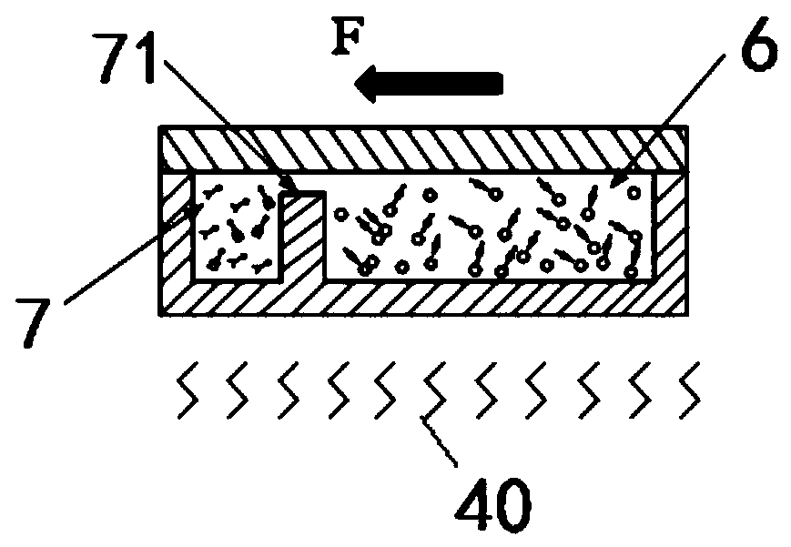
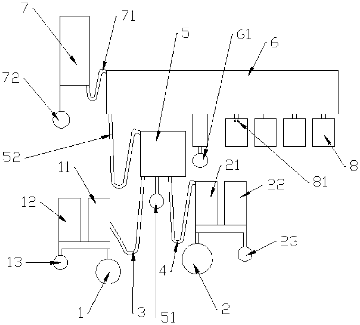
[0105] Embodiment 1: as Figure 2 to Figure 6 As shown, the number of liquid storage tanks 8 is multiple, and the lower end of the liquid storage tank 8 is provided with a piercing protrusion 81 that punctures the prepackaged water box 30 near the end of the detection tank 6, and the piercing protrusion 81 is located at Directly below the communication port between the liquid storage tank 8 and the detection tank 6, the packaging film side of the pre-packaged water box 30 is set towards the piercing protrusion 81. The internal structure of each liquid storage tank 8 is the same, and the pre-packaged water box 30 is used to realize cleaning. Liquid storage and release.

Embodiment 2

[0106] Embodiment 2: as Figure 21 As shown, the number of liquid storage tanks 8 is multiple and connected. The liquid storage tank 8 on the side away from the incubation tank 5 communicates with the diluent overflow tank 22 through the first multiple capillary flow channel 9. The first multiple capillary The flow channel 9 is provided with a first cut-off valve 91, the liquid storage tank 8 on the side away from the incubation tank 5 communicates with the detection tank 6 through the fourth capillary flow channel, and the liquid storage tank 8 on the side close to the incubation tank 5 passes through the second multi-capillary flow channel. The heavy capillary channel 84 communicates with the detection groove 6, and the second multiple capillary channel 84 is provided with a second stop valve, and the distance between the second multiple capillary channel 84 and the center of the substrate 10 is smaller than that of the first multiple capillary channel 9 Distance from the ce...

Embodiment 2

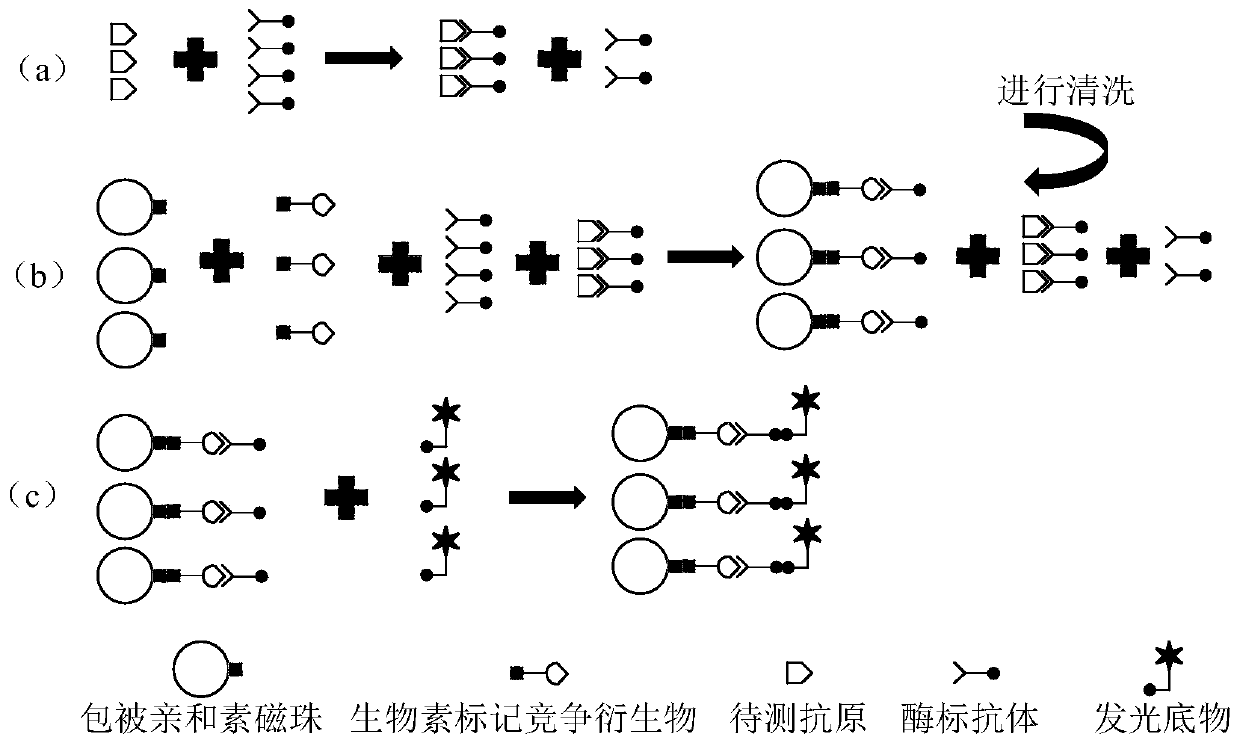
[0128] For example 2: if Figure 21 ~ Figure 33 As shown, in the actual practical process, the enzyme-labeled antibody freeze-dried reagent pellets are pre-packaged in the incubation tank 5, the luminescent substrate reagent freeze-dried pellets are pre-packaged in the cleaning solution quantitative tank on the far right, and the biotin-labeled The competition derivative freeze-dried reagent pellets and the freeze-dried reagent pellets coated with avidin magnetic beads are prepackaged in the detection groove 6 .

[0129] S1: Put a sufficient amount of sample to be tested in the sample adding tank, the sample can be blood sample, urine, sweat, etc., add a sufficient amount of purified water in the diluent sample adding tank, the purified water needs to be purified, specific Sterilization is also required during the test;

[0130] S2: Place the microfluidic chip on the centrifugal platform and fix it, and the motor starts to rotate. Under the action of centrifugal force, the sa...


PUM

PropertyMeasurementUnit
thicknessaaaaaaaaaa

Abstract

The invention provides a micro-fluidic chip for chemiluminescence detection, and a using method and a reagent cleaning method thereof, and belongs to the field of biochemical testing devices. The micro-fluidic chip comprises a substrate and a cover plate which form a sealing environment and are used for a micro-fluid to flow, the substrate is covered with the cover plate, and the substrate comprises: a sample adding hole and a diluted solution adding hole at the first layer; a sample quantification groove, a sample overflow groove, a diluted solution quantification groove and a dilution overflow groove at the second layer; an incubation groove at the third layer, solution storage grooves at the fourth layer, a detection groove at the fifth layer and a waste liquid groove at the sixth layer, wherein the sample quantification groove is communicated with the incubation groove, the diluted solution quantification groove is communicated with the incubation groove, the incubation groove is communicated with the detection groove, and the detection groove is communicated with the waste liquid groove through a hydrophobic flow channel. The separation, mixing and detection of a liquid is realized without repeatedly adding a sample, and the whole process is automatically completed, so the efficiency is increased, and the cost is realized; and the cleaning of a reaction reagent is realized, so the working efficiency is increased.

Description

technical field [0001] The invention belongs to the field of biochemical testing equipment, and relates to a microfluidic chip for chemiluminescence detection, a use method, and a reagent cleaning method. Background technique [0002] Microfluidic chip technology is a new technology for precisely manipulating and controlling nanoliter and picoliter fluids (biological sample fluids) in micron-scale flow channels. The application of this technology can make sample preparation, The basic operation units such as reaction, separation, detection, cell culture, sorting, and lysis are integrated or basically integrated on a chip of several square centimeters (or even smaller), and a network of microfluidic channels is formed to control the flow of fluid throughout the system. A technical platform used to replace various functions of conventional chemical or biological laboratories. The basic feature and biggest advantage of microfluidic lab-on-a-chip is the flexible combination and...

Claims


Application Information

Patent Timeline
Patent Type & Authority Applications(China)
IPC IPC(8): B01L3/00G01N21/76G01N33/58
CPCB01L3/50273B01L3/502723B01L3/502792G01N33/58G01N21/76B01L2200/0684B01L2200/10B01L2300/0887B01L2300/161B01L2300/168B01L2400/0409B01L2400/0406Y02A50/30
Inventor 康之裔
Owner 天津诺迈科技有限公司
Why Eureka
Try Eureka