High-temperature-resisting CO2 laser antireflection film and preparing method thereof

A technology of high temperature resistance and anti-reflection coating, which is applied in the direction of ion implantation plating, coating, metal material coating technology, etc., can solve the problems of poor temperature resistance and few reports of high temperature resistance, and achieve firm film layer and adhesion performance Excellent, well-designed effects

Active Publication Date: 2019-07-12
NANJING WAVELENGTH OPTO ELECTRONICS SCI & TECH CO LTD
View PDF6 Cites 1 Cited by
  • Summary
  • Abstract
  • Description
  • Claims
  • Application Information

AI Technical Summary

Problems solved by technology

Poor temperature resistance is the current CO 2 The ubiquitous defects of laser anti-reflection coati

Method used


Image

  • High-temperature-resisting CO2 laser antireflection film and preparing method thereof
  • High-temperature-resisting CO2 laser antireflection film and preparing method thereof
  • High-temperature-resisting CO2 laser antireflection film and preparing method thereof

Examples


Embodiment 1

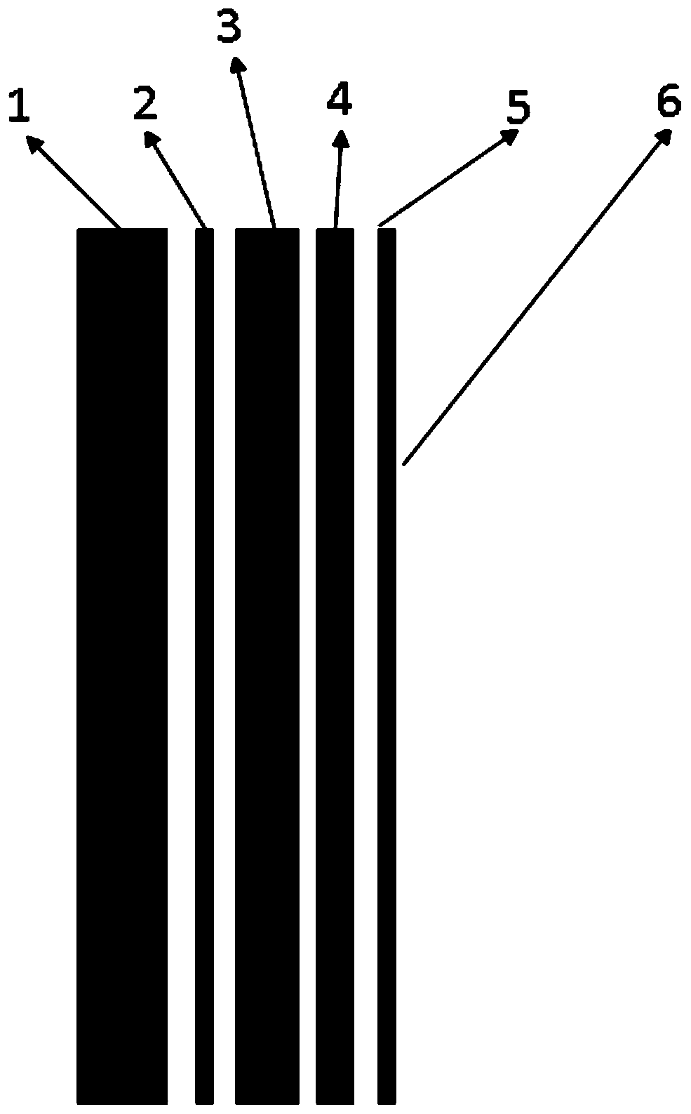
[0037] Such as figure 1 As shown, a high temperature resistant CO 2 The laser anti-reflection coating includes a base layer, on which a first yttrium fluoride layer, a ytterbium calcium fluoride layer, a zinc selenide layer and a second yttrium fluoride layer are sequentially deposited, wherein the first yttrium fluoride layer, fluorine The coverage areas of the calcium ytterbium layer, the zinc selenide layer and the second yttrium fluoride layer are all 98% of the surface area of ​​the base layer.

[0038] The physical thickness of the first yttrium fluoride layer is 96 nanometers; the physical thickness of the ytterbium calcium fluoride layer is 866 nanometers; the physical thickness of the zinc selenide layer is 242 nanometers; the physical thickness of the second yttrium fluoride layer is 97 nanometers; The bottom layer is a zinc selenide base layer with a thickness of 3mm.

[0039] The above high temperature resistant CO 2 The preparation method of the laser anti-refl...

Embodiment 2

[0043] Such as figure 1 As shown, a high temperature resistant CO 2 The laser anti-reflection coating includes a base layer, on which a first yttrium fluoride layer, a ytterbium calcium fluoride layer, a zinc selenide layer and a second yttrium fluoride layer are sequentially deposited, wherein the first yttrium fluoride layer, fluorine The coverage areas of the calcium ytterbium layer, the zinc selenide layer and the second yttrium fluoride layer are all 98% of the surface area of ​​the base layer.

[0044] The physical thickness of the first yttrium fluoride layer is 98 nanometers; the physical thickness of the ytterbium calcium fluoride layer is 863 nanometers; the physical thickness of the zinc selenide layer is 246 nanometers; the physical thickness of the second yttrium fluoride layer is 99 nanometers; The bottom layer is a zinc selenide base layer with a thickness of 3 mm.

[0045] The above high temperature resistant CO 2 The preparation of the laser anti-reflection...


PUM

PropertyMeasurementUnit
Physical thicknessaaaaaaaaaa

Abstract

The invention discloses a high-temperature-resisting CO2 laser antireflection film and a preparing method thereof. The high-temperature-resisting CO2 laser antireflection film comprises a base layer,a first yttrium fluoride layer, a ytterbium fluoride calcium layer, a zinc selenide layer and a second yttrium fluoride layer are sequentially deposited on the base layer, and the coverage area of each of the first yttrium fluoride layer, the ytterbium fluoride calcium layer, the zinc selenide layer and the second yttrium fluoride layer accounts for 95% or above of the surface area of the base layer. The high-temperature-resisting CO2 laser antireflection film is simple in structure and exquisite in design, through combination of the four layers including the first yttrium fluoride layer, theytterbium fluoride calcium layer, the zinc selenide layer and the second yttrium fluoride layer, the characteristics that high temperature resistance is achieved, the transmittance rate is high, filmlayers are firm, stress between the film layers is complementary, and the film layers are not prone to fracture are achieved, and the situation of continuous work of elements under the high-temperature condition can be achieved; and materials used in various layers are free of radioactivity, and harm cannot be caused to operators or the environment.

Description

technical field [0001] The invention relates to a high temperature resistant CO 2 Laser anti-reflection film and preparation method thereof, belonging to CO 2 The field of laser anti-reflection coating. Background technique [0002] In recent years, with the development of the information industry, materials such as ceramics, glass, printed circuit boards, and organic matter have been used in large quantities, and the processing of these materials has become a research hotspot. For this reason, CO 2 Laser technology is being paid more and more attention. [0003] The laser thin film is not only an important component in the laser system, but also the weakest link among all components. The performance of the laser thin film largely determines the performance of the laser output. Laser damage to optical components is the bottleneck that limits the development of lasers to high power and high energy, and is also the main reason that affects the service life of components. T...

Claims


Application Information

Patent Timeline
IPC IPC(8): C23C14/06C23C14/22C23C14/28
CPCC23C14/0694C23C14/0629C23C14/28C23C14/221Y02P70/50
Inventor 李全民陈莉朱敏王国力吴玉堂
Owner NANJING WAVELENGTH OPTO ELECTRONICS SCI & TECH CO LTD
Why Eureka
Try Eureka