Excavation construction method of silty foundation pit

A construction method and silt-based technology, which is applied in excavation, infrastructure engineering, soil protection, etc., can solve problems such as inability to meet construction period requirements, low efficiency of construction machinery and equipment, and long waiting time for shutdown, so as to shorten construction time. , Improving construction efficiency and ensuring safety

Active Publication Date: 2019-12-13
国能大渡河猴子岩发电有限公司 +1
View PDF6 Cites 0 Cited by
  • Summary
  • Abstract
  • Description
  • Claims
  • Application Information

AI Technical Summary

Problems solved by technology

In this project, due to the narrowness of the river valley and the narrow excavation construction surface, as well as the large amount of rain in the flood season, the "drying" process in the conventional traditional "dig-sun-dig" construction process in the past required a long and uncertain waiting time. Not only can it not meet the construction period requirements of this project, but also the efficiency of construction machinery and equipment is relatively low

Method used


Image

  • Excavation construction method of silty foundation pit
  • Excavation construction method of silty foundation pit
  • Excavation construction method of silty foundation pit

Examples


Embodiment 1

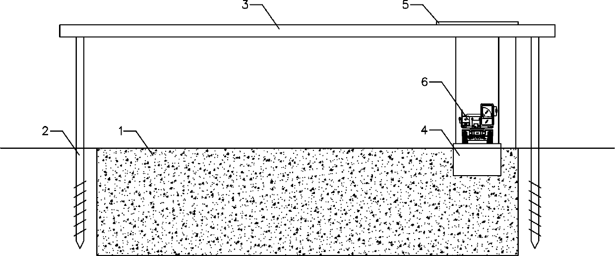
[0040] Such as Figure 1-2 Among them, a muddy foundation pit excavation construction method, the excavator 6 and the dump truck 7 are hoisted by a bridge crane, and the excavation of the foundation pit is carried out in blocks and layers by riprap and silt filling;

[0041] Specifically include the following steps:

[0042] 1) Define the area to be excavated 1, and drive piles 2 around the area to be excavated 1 with a pile driver;

[0043] 2) Hoist and install the bridge frame 3 and the bridge machine 5 above the pile 2;

[0044] 3) Fix the work platform plate 4 on the hoisting rope 19 of the bridge crane 5;

[0045] 4) Drive the excavator 6 onto the work platform plate 4;

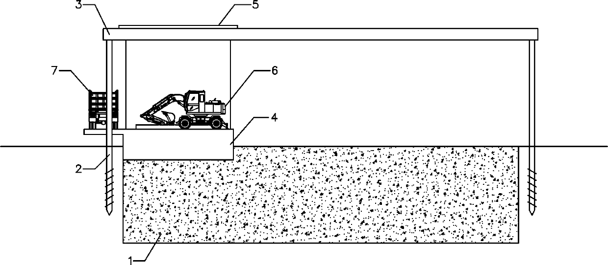
[0046] 5) Throw and fill gravel into the area 1 to be excavated by dump truck 7;

[0047] 6) After the gravel dumping operation is completed, use the excavator 6 to grind the gravel into the area 1 to be excavated;

[0048] 7) Carry out the foundation pit excavation operation of the area 1 to be exc...

Embodiment 2

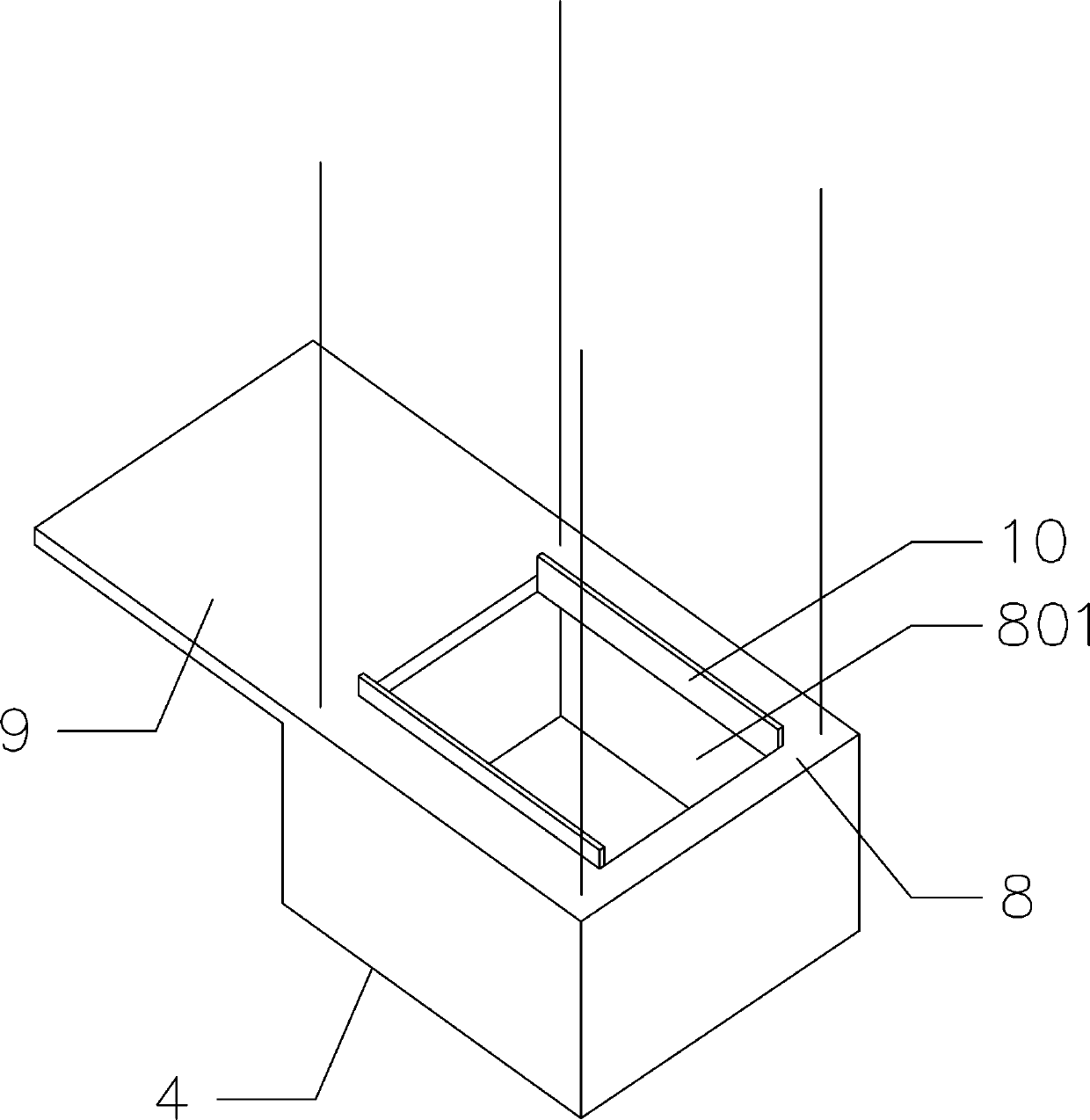
[0051] Such as Figure 3-4 On the basis of Embodiment 1, the working platform plate 4 includes an excavator working platform 8 and a dump truck parking platform 9, and the dump truck parking platform 9 is fixed on one side of the excavator working platform 8;

[0052] The excavator work platform 8 is provided with a downward lower side plate 11 around, and the top surface of the excavator work platform 8 is provided with a work hole 801, and the lower side plate 11 of the excavator work platform 8 includes a constant width plate section 111 in the upper half. And the widened plate section 112 in the lower half, the plate width of the widened plate section 112 gradually decreases from top to bottom.

[0053] In a preferred solution, the height of the lower side plate 11 is 3-5m.

[0054] In a preferred solution, side baffles 10 for positioning the excavator 6 are provided on the top surface of the excavator working platform 8 on both sides of the working hole 801 .

Embodiment 3

[0056] Such as Figure 5 Among them, the bridge frame 3 is composed of a plurality of section steels 12, the section steels 12 on both sides are provided with a first rail 13, the cart 14 of the bridge machine 5 is arranged on the first rail 13 and passes through the cart motor 15 Drive to realize movement along the direction of the first track 13;

[0057] Be provided with crossbeam 16 on cart 14, be provided with second track 17 on the top surface of crossbeam 16, the hoist trolley 18 of bridge crane 5 is arranged on the second track 17 and can move along the second track 17 direction.

[0058] In a preferred solution, the section steel 12 at both ends of the bridge frame 3 is made of I-beam, the section steel 12 and the beam 16 on both sides of the bridge frame 3 are made of channel steel, and the grooves of the channel steel are directly used as tracks.


PUM


Abstract

The invention provides a muddy foundation pit excavation construction method. An excavator and a dump truck are hoisted through a bridge crane, and foundation pit excavation operation is conducted instone dumping and mud filling modes and in partitioning and layering modes. The muddy foundation pit excavation construction method specifically comprises the following steps that (1) a to-be-excavated area is designated, and piles are driven around the to-be-excavated area through a pile driver; (2) a bridge crane frame and the bridge crane are mounted on the upper parts of the piles in a hoistedmode; (3) an operation platform plate is fixedly arranged on a hoisting rope of the bridge crane; (4) the excavator is driven onto the operation platform plate; (5) rock ballast is dumped into the to-be-excavated area through the dump truck; (6) the rock ballast is ground into the to-be-excavated area through the excavator; (7) foundation excavation operation of the to-be-excavated area is conducted through the excavator; and (8) the foundation excavation operation of the to-be-excavated area is conducted in the partitioning and layering modes. By adopting the construction method of stone dumping and mud filling, the bearing ability and water permeability of mud are improved through the rock ballast, the construction demands of transporting while excavating of a foundation pit are met, the excavation construction period of the muddy foundation pit is shortened, and the construction efficiency is improved.

Description

technical field [0001] The invention relates to the field of foundation pit excavation construction, in particular to a muddy foundation pit excavation construction method. Background technique [0002] Existing excavation for soil layers with high moisture content generally adopts drying while digging, and excavation and transportation after water loss forms dry soil. In this project, due to the narrowness of the river valley and the narrow excavation construction surface, as well as the large amount of rain in the flood season, the "drying" process in the conventional traditional "dig-sun-dig" construction process in the past required a long and uncertain waiting time. Not only can it not meet the construction period requirements of this project, but also the efficiency of construction machinery and equipment is relatively low. Contents of the invention [0003] The technical problem to be solved by the present invention is to provide a construction method for the excav...

Claims


Application Information

Patent Timeline
Patent Type & Authority Patents(China)
IPC IPC(8): E02D17/02E02D3/00
CPCE02D3/00E02D17/02
Inventor 柏元武郑正勤朱永国杨小华唐珂费波涛杨吉学童杰李家富李远运
Owner 国能大渡河猴子岩发电有限公司
Why Eureka
Try Eureka