LED flame lamp adopting flame light-emitting assemblies on both sides

A technology of light-emitting components and LED lamp beads, which is applied in the field of LED flame lamps and lighting fixtures, can solve problems such as unfavorable automatic production, poor damage, and complex component structures, so as to save labor and materials, improve production efficiency, and reduce manufacturing costs. Effect

Pending Publication Date: 2019-07-12
HAINING XINCHENG ELECTRONICS CO LTD +1
View PDF0 Cites 1 Cited by
  • Summary
  • Abstract
  • Description
  • Claims
  • Application Information

AI Technical Summary

Problems solved by technology

Currently on the market is a kind of LED flame bulb that imitates the flame effect. It uses LED particles such as 2.8x3.5mm arrays on a flexible PCB circuit board. The flexible PCB board is pasted on a cylindrical tube and fixed to form a flame light source board like corn cobs. Through the driving power supply and control circuit, each LED lamp bead is driven to light and dark to form a series of LED lights on the flame light source board. Change, the light passes through the white plastic bulb to generate a simulated flame. Since these LED lamp beads are arranged in a dot matrix, there is a distance (about 5mm) between the lamp beads and the lamp beads, resulting in this flame bulb in the 2m You can clearly see the light and dark changes of each LED inside the bulb. Only when you can’t see a single LED bead through a certain distance (about more than 2 meters), will there be a flame effect. This kind of The LED flame effect simulated by the LED flame lamp is not realistic enough and blunt. For example, the image distortion caused by the low display pixels of the early LED screen caused the flame effect to be unreal. It can only simulate the effect of flame jumping, but cannot simulate the fog of the flame. bridging effect
Especially for large-sized flame bulbs (such as flame bulbs with E26 / 27 lamp holders), the diameters of the two ports of the LED cylindrical light-emitting body are relatively large (greater than 15mm), and the ports are the light-emitting tops of the bulbs without LED beads, resulting in the top of the bulb There are also dark areas. In addition, the curling of the soft board also causes poor damage. The fixing effect of the soft board is not good and it is pasted by hand. The component structure is complicated. There are many LED lamp beads used in this kind of flame lamp, and the high cost is not conducive to automatic production. , which is not conducive to promotion and application

Method used


Image

  • LED flame lamp adopting flame light-emitting assemblies on both sides
  • LED flame lamp adopting flame light-emitting assemblies on both sides
  • LED flame lamp adopting flame light-emitting assemblies on both sides

Examples


Embodiment 1

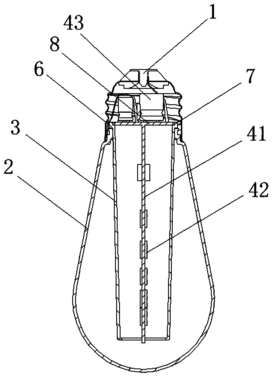
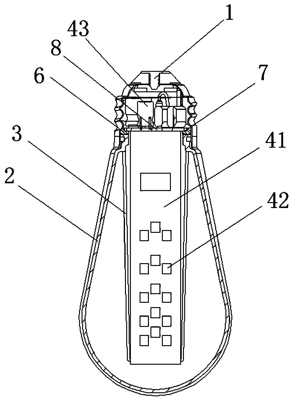
[0032] refer to figure 1 and figure 2 , the present invention is an LED flame lamp using a double-sided flame light-emitting component, including a lamp base 1, a bulb shell 2, a light guide tube 3 and a flame light source plate 4, the inner wall of the lamp base 1 is provided with a bulb shell 2, and the inside of the bulb shell 2 A light guide tube 3 is provided, and a flame light source board 4 is arranged inside the light guide tube 3. The flame light source board 4 includes a double-sided circuit board 41, LED lamp beads 42 and a driving power supply 43. The front and back sides of the double-sided circuit board 41 are welded. There are LED lamp beads 42, and the LED lamp beads 42 and the driving power supply 43 on the flame light source board 4 are respectively welded to two circuit boards, which are split structure flame light source boards, split structure flame light source boards, and double-sided circuit boards 41 are welded with LED lamp beads, the top of the dou...

Embodiment 2

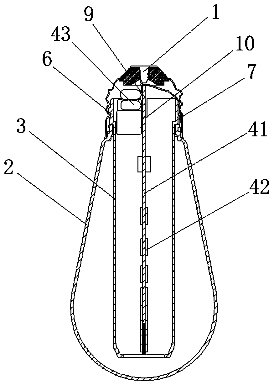
[0034] refer to image 3 , Figure 4 , Figure 5 and Figure 6 In this embodiment, on the basis of the first embodiment, the split structure of the first embodiment is changed into a T-shaped integrated structure. The LED lamp bead 42 and the driving power supply 43 are welded on the same double-sided circuit substrate 41, and the driving power supply 43 Lugs 9 are provided outward on both sides of the end of the double-sided circuit board 41. The double-sided circuit board 41 has a T-shaped structure. The lugs 9 are embedded in the slot 10 of the light guide tube 3 and fixed. One end and the center hole of one end of the light guide tube 3 are inscribed and clamped. The bulb shell 2 is made of plastic material. The top of the light guide tube 3 can be provided with external threads or not, which can make the structure of the LED bulb or lamp simpler and more optimized. Improve assembly efficiency, reduce manual labor, and its cost performance is more advantageous.


PUM


Abstract

The invention discloses an LED flame lamp adopting flame light-emitting assemblies on both sides. The LED flame lamp comprises a lamp cap, a bulb shell, a light guide barrel and a flame light source board, wherein the bulb shell is arranged at the opening of the inner wall of the lamp cap, the light guide barrel is arranged in the bulb shell, the flame light source board is arranged in the light guide barrel, the flame light source board comprises a double-side circuit substrate, LED lamp beads and a drive power supply, the LED lamp beads are welded to the front and back sides of the double-side circuit substrate, the LED lamp beads and the drive power supply on the flame light source board can be welded to one double-side circuit substrate, so that the flame light source board in an integrated structure is formed, or the LED lamp beads and the drive power supply can be respectively welded to two circuit substrates, so that the flame light source board in split structures is formed. For the LED flame lamp adopting the flame light-emitting assemblies on both sides, the use number of the LED lamp beads can be greatly reduced, thus the manufacturing cost is reduced, in addition, the light emitting effect is softer, the luminance of the dark area is improved, the fixing effect of the flame light source board in the light guide barrel is improved, then the assembly efficiency can beimproved, the manual labor is reduced, the rejection rate is reduced, the automatic production is realized, and the market competitiveness of the product is strong.

Description

[0001] 【Technical field】 [0002] The invention relates to the technical field of lighting fixtures, in particular to the technical field of an LED flame lamp using a double-sided flame light-emitting component. [0003] 【Background technique】 [0004] With the development of society and the improvement of people's material living standards, people's life taste and aesthetic level are also gradually improving. Bulbs and lighting decorations, as daily necessities commonly used by people, play an irreplaceable role in people's daily life. People's demand for these lighting and lighting decoration products is becoming more and more detailed, and the appreciation requirements are getting higher and higher. The very retro flame effect lighting can add more atmosphere and beauty to people's living space. [0005] Flame is the visible light or other physical manifestations that appear in the chemical process in which fuel and air are quickly transformed into combustion products. It i...

Claims


Application Information

Patent Timeline
Patent Type & Authority Applications(China)
IPC IPC(8): F21S10/04F21V23/00F21V5/00F21V8/00F21V5/02F21Y115/10
CPCF21S10/04F21V5/00F21V5/02F21V23/003F21V2200/00F21Y2115/10
Inventor 潘建新伍连李洪波
Owner HAINING XINCHENG ELECTRONICS CO LTD
Why Eureka
Try Eureka