Electromagnetic camouflage metamaterial and application thereof
A metamaterial and electromagnetic technology, applied in the field of electromagnetic metamaterials, can solve the problems of limited number of reflected phases of the unit structure, inability to directly coat the metamaterial structure, low degree of freedom in metamaterial design, etc. Design flexibility, the effect of increased numbers
- Summary
- Abstract
- Description
- Claims
- Application Information
AI Technical Summary
Problems solved by technology
Method used
Image
Examples
Embodiment 1
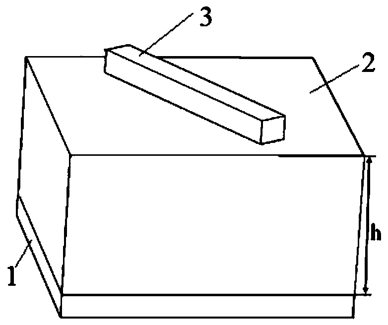
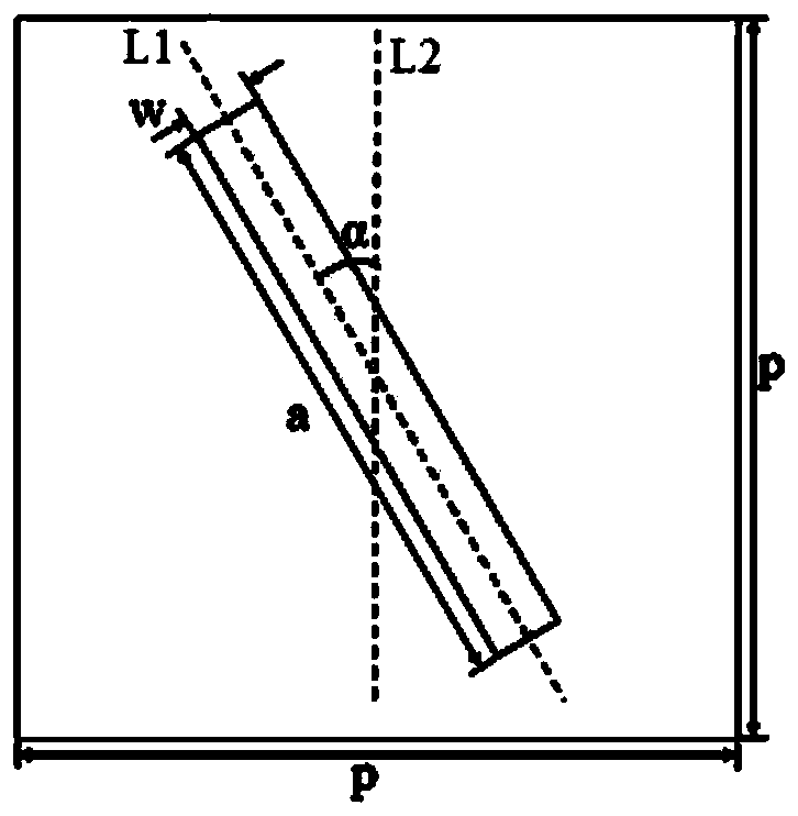
[0043] Figure 5a It is a three-dimensional diagram of electromagnetic camouflage metamaterials with metal patch lengths of 4mm and 6mm. In order to expand the reduced bandwidth of the metamaterial RCS, two metal patches with lengths of 4mm and 6mm are used. Metal bottom layer length×width×height=150mm*150mm*0.035mm, middle dielectric layer length×width×height=150mm*150mm*3mm. The metal patch area on the surface of the metamaterial accounts for 3.33%, 250 metal patches with a length of 4mm, 250 metal patches with a length of 6mm, and all metal patches are 0.3mm wide and 0.035mm thick. The metal patches are randomly distributed on the surface of the metamaterial and rotated arbitrarily, forming a large number of phase gradient units.
[0044] Figure 5b is the far-field two-station RCS reduction result of the electromagnetic camouflage metamaterial when the electric field polarization direction of the vertical incident wave is along the x-axis and y-axis respectively. The m...
Embodiment 2
[0046] Figure 6a It is a three-dimensional diagram of electromagnetic camouflage metamaterials with metal patch lengths of 4mm and 7mm. In order to expand the bandwidth of the metamaterial RCS and reduce the bandwidth, Case 2 uses metal patches with lengths of 4mm and 7mm respectively. The length × width × height of the metal bottom layer = 150mm × 150mm × 0.035mm, and the length × width × height of the intermediate dielectric layer = 150mm × 150mm × 3mm. The proportion of metal patches on the surface of the metamaterial is 3.67%, 250 metal patches with a length of 4mm, and 250 metal patches with a length of 7mm. The width of the metal patch is 0.3mm and the thickness is 0.035mm. The metal patches are randomly distributed on the surface of the dielectric layer 2 and rotated arbitrarily.
[0047] Figure 6b is the far-field two-station RCS reduction result of the electromagnetic camouflage metamaterial when the electric field polarization direction of the vertical incident ...
Embodiment 3
[0049] Figure 7a It is a three-dimensional diagram of electromagnetic camouflage metamaterials with metal patch lengths of 3mm and 8mm. In this embodiment, the metal patch 3 has two lengths, namely a metal patch with a length of 3 mm and a metal patch with a length of 8 mm. The length×width×height of the metal bottom layer=150mm*150mm*0.035mm, the length×width×height of the dielectric layer=150mm*150mm*3mm. The proportion of metal patches on the surface of the metamaterial is 3.67%. There are 250 metal patches with a length of 3mm and 250 metal patches with a length of 8mm. The width of the metal patch is 0.3mm and the thickness is 0.035mm. The metal patches 3 are randomly distributed on the surface of the dielectric layer 2 and rotated arbitrarily within 0-180°.
[0050] Figure 7b is the far-field two-station RCS reduction result of the electromagnetic camouflage metamaterial when the electric field polarization direction of the vertical incident wave is along the x-axis...
PUM
| Property | Measurement | Unit |
|---|---|---|
| Length | aaaaa | aaaaa |
| Width | aaaaa | aaaaa |
| Thickness | aaaaa | aaaaa |
Abstract
Description
Claims
Application Information
 - R&D
- Intellectual Property
- Life Sciences
- Materials
- Tech Scout
- Unparalleled Data Quality
- Higher Quality Content
- 60% Fewer Hallucinations
Browse by: Latest US Patents, China's latest patents, Technical Efficacy Thesaurus, Application Domain, Technology Topic, Popular Technical Reports.
© 2025 PatSnap. All rights reserved.Legal|Privacy policy|Modern Slavery Act Transparency Statement|Sitemap|About US| Contact US: help@patsnap.com


