Optical phase locking method based on microwave photon frequency division

A microwave photon and phase-locking technology, which is applied in the field of optical phase-locking, can solve problems such as locking phase jitter, reduce jitter, reduce the difficulty of phase identification, and overcome the effect that is difficult to apply to high-frequency microwave signals

Active Publication Date: 2019-07-12
NANJING UNIV OF AERONAUTICS & ASTRONAUTICS
View PDF5 Cites 10 Cited by
  • Summary
  • Abstract
  • Description
  • Claims
  • Application Information

AI Technical Summary

Problems solved by technology

[0007] The technical problem to be solved by the present invention is to overcome the deficiencies of the prior art and provide an optical phase-locking method based on microwave photon frequency division, which can overcome the problem of phase jitter in traditional dual-laser locking and reduce the requirements for phase detectors, thereby achieving high Frequency stable microwave signal output

Method used


Image

  • Optical phase locking method based on microwave photon frequency division
  • Optical phase locking method based on microwave photon frequency division
  • Optical phase locking method based on microwave photon frequency division

Examples


Embodiment Construction

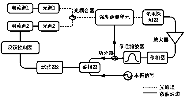
[0027] Aiming at the problem of phase jitter existing in the prior art and the difficulty of accurately phase-detecting high-frequency microwave signals, the solution of the present invention is to use OEO-based microwave photon frequency division technology to divide the difference frequency signal of the dual light source , and then use the frequency division signal and the phase discrimination result of the local oscillator signal to perform feedback control on the light source, thereby realizing phase locking of the two light sources. On the one hand, it can greatly reduce the requirements for the phase detector and overcome the problem that the phase detector is difficult to apply to high-frequency microwave signals; on the other hand, it can effectively overcome the problem of phase jitter and reduce phase noise.

[0028] Specifically, the optical phase-locking method of the present invention is specifically as follows: input the coupling signal of the optical signals out...


PUM


Abstract

The invention discloses an optical phase locking method based on microwave photon frequency division. The method comprises the steps of: inputting coupling signals of optical signals output by two monochromatic light sources to be subjected to phase lock into a photoelectric oscillation loop, wherein the oscillation mode of microwave signals with the frequency as shown in the description in the photoelectric oscillation loop is bandpass, and [omega]0 is the difference of the output frequencies of the two monochromatic light sources; forming positive feedback oscillation by the oscillation modeof microwave signals with the frequency as shown in the description in the photoelectric oscillation loop so as to obtain stable micro signals with the frequency as shown in the description; performing phase demodulation for the micro signals with the frequency as shown in the description output by the photoelectric oscillation loop and the local oscillator micro signals, and employing a phase demodulation result after elimination of high-frequency components to perform feedback control for the phase of the at least one monochromatic light source so as to achieve the phase locking of the twomonochromatic light sources. The present invention further discloses an optical phase locking device based on microwave photon frequency division which can overcome the problem of the locking phase jitter and reduce the requirement on phase demodulation so as to achieve high-frequency and stable micro wave signal output.

Description

technical field [0001] The invention relates to an optical phase-locking method, in particular to an optical phase-locking method and device based on microwave photon frequency division. Background technique [0002] Optical communication is the combination of microwave and optoelectronics. Early telephone and telegraph wireless communication, signal generation, transmission and reception all used microwave devices. At the beginning, low-frequency electromagnetic waves were used, because the frequency range was small and the transmission channel capacity was small. The solution is to increase the frequency of transmission signals, the higher the frequency, the more spectrum resources. However, high-frequency signals have a large propagation loss in the air and are easily blocked by obstacles. If it is transmitted by wire, the loss of the cable is large, and long-distance transmission is a problem. The emergence of optical fiber communication has solved these problems very...

Claims


Application Information

Patent Timeline
Patent Type & Authority Applications(China)
IPC IPC(8): H01S3/098H01S3/13H04B10/54
CPCH01S3/1106H01S3/1305H04B10/54
Inventor 潘时龙刘鸿飞刘世锋吕凯林康晓晨朱楠
Owner NANJING UNIV OF AERONAUTICS & ASTRONAUTICS
Why Eureka
Try Eureka