
Stereoscopic transition structure based on air gap waveguide in complex feed network

A technology of air gap and feed network, applied in the direction of waveguide, electrical components, waveguide type devices, etc., can solve the problems of no mention of insertion loss, no mention of, and reduction of insertion loss, and achieve low loss and convenient integration , The effect of reducing the requirements of machining accuracy

Active Publication Date: 2019-07-16
NANJING UNIV OF SCI & TECH
View PDF5 Cites 8 Cited by
  • Summary
  • Abstract
  • Description
  • Claims
  • Application Information

AI Technical Summary

Problems solved by technology

[0004] Davoud Zarifi, Ali Farahbakhsh et al. in "Design and Fabrication of a High-Gain 60-GHz Corrugated Slot Antenna Array With Ridge Gap WaveguideDistribution Layer" (IEEE Trans. Antennas Propag, vol. 64, no. 7, pp. 2905-2913, July, 2016.) In the article, a 16 x 16 antenna transition transmission method from RGW to WR-15 is designed. The measured gain is greater than 32.5dBi, and the antenna efficiency exceeds 70%, but it does not mention how to reduce the insertion loss.
[0005] A. Farahbakhsh, D. Zarifi, etc. in "60-GHz groove gap waveguide basedwideband H -plane power dividers and transitions: For use in high-gain slotarray antenna" (IEEE Trans. Microw. Theory Techn, vol. 65, no. 11 , pp. 4111–4121, Nov. 2017.) In this paper, a power divider based on the groove gap waveguide (GGW) technology is designed, the gain is greater than 32.5dBi, and the total radiation efficiency exceeds 80% , but did not mention how to reduce the insertion loss

Method used


Image

  • Stereoscopic transition structure based on air gap waveguide in complex feed network
  • Stereoscopic transition structure based on air gap waveguide in complex feed network
  • Stereoscopic transition structure based on air gap waveguide in complex feed network

Examples


Embodiment Construction

[0023] The present invention will be described in further detail below in conjunction with the accompanying drawings.

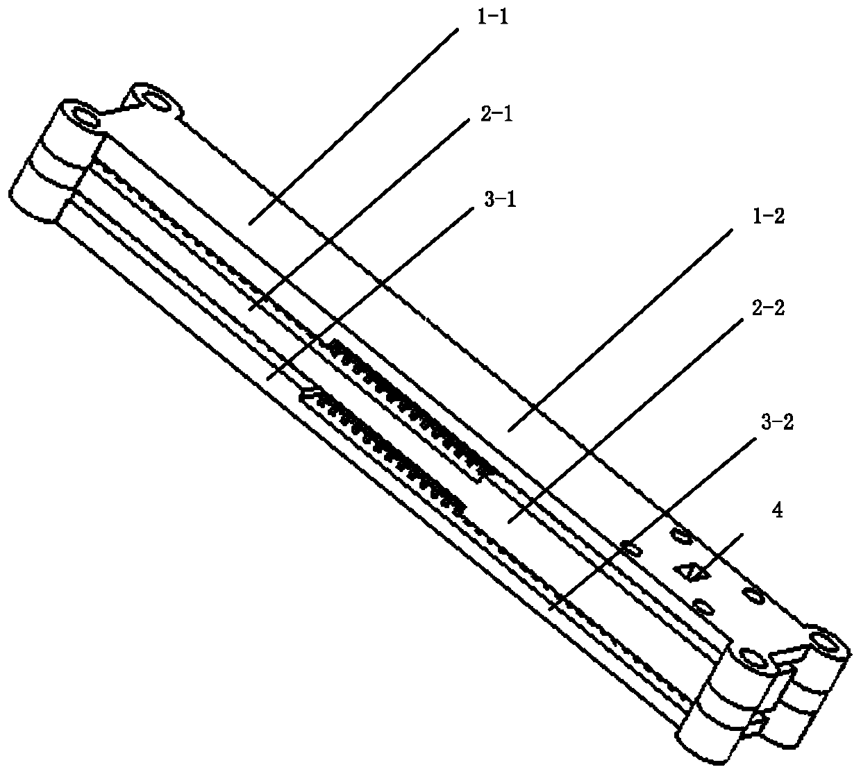
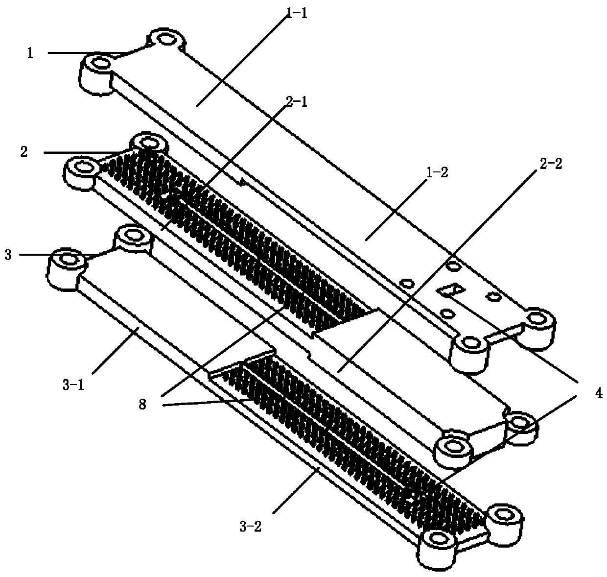
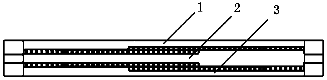
[0024] combine Figure 1 to Figure 5 , the three-dimensional transition structure based on the air gap waveguide in the complex feeding network of the present invention includes a top layer board 1, an intermediate layer board 2 and a bottom layer board 3, and the middle layer board 2 is arranged between the top layer board 1 and the bottom layer board 3, The three are connected by bolts.

[0025] The top board 1 includes a first ideal conductance wall 1-1, a first artificial magnetic conductance wall 1-2, a ridge-gap waveguide structure 8, an air-gap waveguide-coupling slot matching structure 7, a rectangular waveguide transition structure 4, and several electromagnetic bandgap EBGs Structure 5, one end of the first ideal conductance wall 1-1 is directly connected to one end of the first artificial magnetic conductance wall 1-2, the length of the first idea...


PUM


Abstract

The present invention discloses a stereoscopic transition structure based on an air gap waveguide in a complex feed network, and belongs to microwave components. The stereoscopic transition structurecomprises a top plate, an intermediate plate and a bottom plate, wherein the intermediate plate is arranged between the top plate and the bottom plate in fixed connection to each other. In particular,the present invention adopts an ideal conductive wall, an artificial magnetic wall, ridge gap waveguide structures, air gap waveguide-coupling gap match structures, rectangular waveguide transition structures, national standard BJ400 rectangular waveguide coupling gaps and electromagnetic band gap EBG structures. The electromagnetic wave can only be transmitted along the specific guide structureformed by the rectangular waveguide transition structures and the ridge gap waveguide structures of the top plate, the air gap waveguide-coupling gap match structures and the national standard BJ400 rectangular waveguide coupling gaps, the electromagnetic band gap EBG structures are periodically arranged around the ridge gap waveguide for limiting the leakage of electromagnetic wave to the surrounding. The present invention achieves transmission characteristics with low insertion loss over a wide bandwidth.

Description

technical field [0001] The invention belongs to microwave components, in particular to a three-dimensional transition structure based on an air gap waveguide in a complex feeding network. Background technique [0002] In the past decade, a new transmission structure, the gap waveguide technology, has been proposed in the field of millimeter wave (mmW) applications. Based on this technology, a large number of microwave devices have been produced, such as antennas, filters, feed networks and couplers. The gap waveguide is realized by two parallel metal plates. The electromagnetic bandgap array is fabricated on the lower metal plate to form an artificial magnetic conduction surface, and the upper metal surface is an ideal electric wall. Except along some specific guiding structures, such as ridges and grooves, no electromagnetic waves can pass through the above structures if the gap between the top of the pin and the upper plate is less than a quarter wavelength. [0003] Lik...

Claims


Application Information

Patent Timeline
Patent Type & Authority Applications(China)
IPC IPC(8): H01P3/18H01Q1/50H01Q21/00
CPCH01P3/18H01Q1/50H01Q21/0006
Inventor 贾方秀李雨辰曹阳许鹏飞姜勋郭闯唐伟黄盼殷婷婷
Owner NANJING UNIV OF SCI & TECH
Learn More