
Design method of tdicmos imaging unit

A technology of imaging unit and design method, applied in electrical components, radiation control devices, pulse technology, etc., can solve problems such as poor stability, complex design of TDICMOS imaging unit, etc., to avoid reflection, avoid difficulty in acquisition, and avoid excessive voltage variation big effect

Inactive Publication Date: 2020-10-16
CHANGCHUN INST OF OPTICS FINE MECHANICS & PHYSICS CHINESE ACAD OF SCI
View PDF7 Cites 0 Cited by
  • Summary
  • Abstract
  • Description
  • Claims
  • Application Information

AI Technical Summary

Problems solved by technology

[0003] The invention provides a design method of a TDICMOS imaging unit in order to solve the problems of complex design and poor stability of the existing TDICMOS imaging unit

Method used


Image

  • Design method of tdicmos imaging unit
  • Design method of tdicmos imaging unit
  • Design method of tdicmos imaging unit

Examples


specific Embodiment approach 1

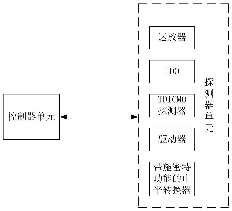
[0021] Specific implementation mode 1. Combination Figure 1 to Figure 5 In this embodiment, the design method of the TDICMOS imaging unit includes two parts: a controller unit and a detection unit. The detector unit includes a TDICMOS detector, an operational amplifier, an LDO, a driver with a Schmitt function, and a level shifter with a Schmitt function. The controller unit generates the control signals required by the detector unit and receives the digital image data output by the detector unit. The operational amplifier and LDO generate the operating voltage required by the detector, the driver with Schmitt function generates the driving signal required by the TDICMOS detector, and the level shifter with Schmitt function generates the control signal required by the TDICMOS detector .

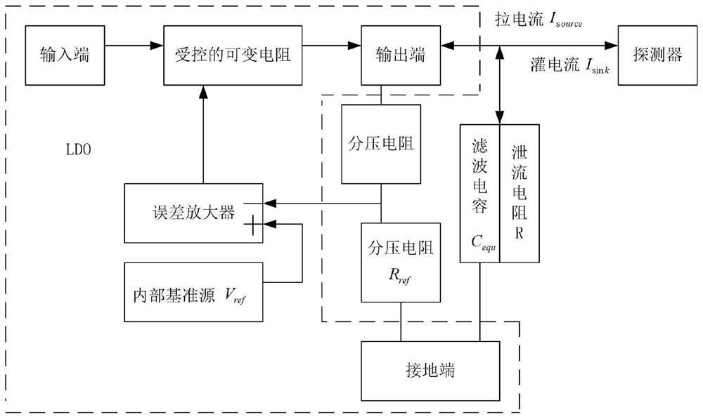
[0022] In this embodiment, two methods are used for the power supply of the pixel part with sinking current. The first method is the existing method, which is generated by the method of "r...


PUM


Abstract

The design method of a TDICMOS imaging unit relates to a design method of a TDICMOS imaging unit, which solves the problems of complex design and poor stability of the existing TDICMOS imaging unit, including a controller unit and a detector unit; the controller unit generates a detector unit The required control signal, and receive the digital image data output by the detector unit; the detector unit includes a TDICMOS detector, an operational amplifier, an LDO, a driver with a Schmitt function, and a level shifter with a Schmitt function device; the present invention is respectively designed for the power supply of the pixel part with the sinking current, the transmission of the digital input control signal, the generation method of the charge transfer driving signal, the placement method of the via hole in the high-density area and the processing of the multi-layer ground plane, the maximum Maximize the utilization area of ​​the circuit board, improve the integrity of the control drive signal and power supply, and avoid risks such as voltage breakdown and virtual soldering.

Description

technical field [0001] The invention relates to a design method of a TDICMOS imaging unit, in particular to a design method of a highly reliable TDICMOS imaging unit in a size-limited environment. Background technique [0002] For the charge domain TDICMOS imaging design, the detector not only includes the photosensitive part of the TDICCD detector and the gate of the charge transfer, but also includes the related double sampling and digital-to-analog conversion circuit, timing generator, bias, SPI register and LVDS There are many functional parts, such as receivers and transmitters. Due to the many functional parts of the TDICMOS detector, the TDICMOS imaging design is complex, and careful design inspection is required to ensure stable and reliable work. Contents of the invention [0003] The invention provides a design method of the TDICMOS imaging unit in order to solve the problems of complex design and poor stability of the existing TDICMOS imaging unit. [0004] Th...

Claims


Application Information

Patent Timeline
Patent Type & Authority Patents(China)
IPC IPC(8): H03K3/0233H01L27/146
CPCH01L27/146H03K3/02337
Inventor 余达刘金国徐东苗健宇杨亮胡庆龙王玉龙
Owner CHANGCHUN INST OF OPTICS FINE MECHANICS & PHYSICS CHINESE ACAD OF SCI
Learn More