Fiber reinforce plastic (FRP) sectional material beam column joint capable of being assembled rapidly

A beam-column joint and profile technology, applied in the direction of building and building structure, can solve the problems of reduced column bearing capacity, difficult pouring, complicated structure, etc., and achieve the effects of good energy dissipation capacity, convenient construction and simple structure

Active Publication Date: 2019-07-26
WUHAN UNIV
View PDF7 Cites 7 Cited by
  • Summary
  • Abstract
  • Description
  • Claims
  • Application Information

AI Technical Summary

Problems solved by technology

[0004] The above-mentioned first two types of joints are complex in structure, difficult to pour, and have the disadvantages of local failure of the column that reduces the bearing capacity
And because there is no steel bar in the new beam (FRP is used instead of steel bar to bear the tensile force), it is not suitable for the node connection of the new prefabricated structural system represented by the FRP tubular concrete column with embedded FRP profile and the box-shaped FRP profile concrete composite beam.
Also because there is no steel in the new rapid assembly structure system, the third type of joint connection (welding and bolting) is not applicable

Method used


Image

  • Fiber reinforce plastic (FRP) sectional material beam column joint capable of being assembled rapidly
  • Fiber reinforce plastic (FRP) sectional material beam column joint capable of being assembled rapidly
  • Fiber reinforce plastic (FRP) sectional material beam column joint capable of being assembled rapidly

Examples


Embodiment Construction

[0026] Below in conjunction with accompanying drawing and specific embodiment the present invention is described in further detail:

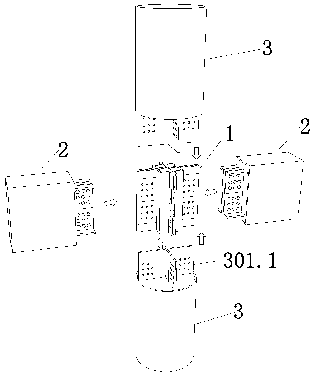
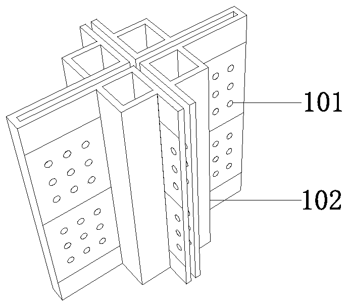
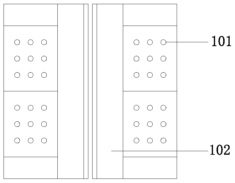
[0027] As shown in the figure, the FRP profile beam-column node that can be assembled quickly is characterized in that it includes a prefabricated node 1, two box-shaped FRP profile concrete composite beams 2, two FRP tubular concrete columns 3 embedded with cross FRP profiles and A number of bolts 4; the prefabricated node 1 is a split cross node, which is composed of two identical nodes to form a cross shape, and a plurality of first bolt holes 101 corresponding to the cross FRP profile of the FRP tubular concrete column 3 are preset in four directions; The first bolt holes 101 are arranged in no less than three columns in the two directions where the cross shape of the precast node 1 is connected to the FRP tubular concrete column 3, and the plurality of first bolt holes 101 are arranged in the other two directions of the cross shape of the pr...


PUM


Abstract

The invention discloses a fiber reinforce plastic (FRP) sectional material beam column joint capable of being assembled rapidly. The FRP sectional material beam column joint capable of being assembledrapidly comprises a FRP pipe concrete column with an embedded cross-shaped FRP sectional material, a box groove FRP sectional material concrete combined beam, a prefabricated joint and a matched bolt. A joint body is composed of two same parts and is assembled with the embedded cross-shaped FRP sectional material, and the beam is connected with the joint through an end part pre-embedded groove shape steel plate. The main construction method of the FRP sectional material beam column joint capable of being assembled rapidly comprises the steps that a column prefabricated FRP pipe and the cross-shaped FRP sectional material are placed in position; the joint is assembled correspondingly with the cross-shaped FRP sectional material extending from the column and the beamless connection direction bolt is tightened; the beam is hoisted in position, the beam end groove steel plate and the joint are opposite to a reserved bolt hole and the bolt is tightened; and a template is arranged in a supporting mode, and concrete in the column and the concrete at the joint are poured. The FRP sectional material beam column joint capable of being assembled rapidly is simple in construction and convenient to construct, can greatly improve the construction efficiency, and is easy to control the quality. Meanwhile, a force transferring route of the joint is distinct, the good energy consumption is achieved, and the safety of a main body structure can be well guaranteed.

Description

technical field [0001] The invention relates to the field of construction engineering, in particular to a fast-assembled FRP profile beam-column node. Background technique [0002] Modern buildings are facing more and more harsh environments such as highly corrosive, alternating wet and dry conditions, which pose a huge threat to the durability of traditional reinforced concrete structures. In order to fundamentally avoid problems such as corrosion, it is extremely effective to replace steel with high-performance composite materials with good corrosion resistance. The FRP material is not only light and high strength, but also has good corrosion resistance and strong designability, so it is a good alternative material. At present, there are many construction application cases using FRP profiles instead of steel, most of which belong to prefabricated structural systems. [0003] In the prefabricated structural system, although beams, columns and other components are easy to ...

Claims


Application Information

Patent Timeline
Patent Type & Authority Applications(China)
IPC IPC(8): E04B1/21
CPCE04B1/215
Inventor 卢亦焱梁鸿骏赵晓博刘真真赵顺波赵鹏抟张登峰
Owner WUHAN UNIV
Why Eureka
Try Eureka