Thin film battery and preparation method thereof

A thin-film battery and electrode technology, applied in the field of thin-film battery and its preparation, can solve the problems of electrolyte leakage, high cost, and inability to obtain thinner thickness, etc., and achieve the effect of excellent mechanical flexibility and excellent electrochemical performance

Active Publication Date: 2019-07-26
ZINERGY SHENZHEN LTD
View PDF7 Cites 1 Cited by
  • Summary
  • Abstract
  • Description
  • Claims
  • Application Information

AI Technical Summary

Problems solved by technology

These two methods either cost a lot, or can only achieve a limited thickness. For example, the conventional pouch battery can reach 1-2mm, and it is impossible to obtain a thinner thickness.
At the same

Method used


Image

  • Thin film battery and preparation method thereof
  • Thin film battery and preparation method thereof

Examples


preparation example Construction

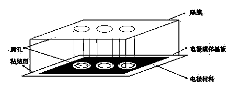
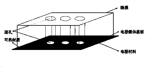
[0029] The invention provides a method for preparing a thin film battery, comprising the following steps:

[0030] A) Print the electrode material at the position away from the edge on the electrode carrier substrate, and leave the pattern of the through hole in the printed electrode pattern to obtain the electrode plate; die-cut at the pattern of the through hole of the electrode plate, so that The electrode plate produces a through hole, and the aperture of the through hole of the electrode plate is smaller than the aperture of the through hole of the electrode pattern; the electrode plate includes a positive electrode plate and a negative electrode plate;

[0031] Die-cutting the diaphragm so that the diaphragm produces a through hole, the aperture of the through hole of the diaphragm is smaller than the aperture of the through hole of the electrode pattern; the aperture of the through hole of the diaphragm is larger than the aperture of the through hole of the electrode pla...

Embodiment 1

[0084] The positive carrier substrate includes:

[0085] Aluminum foil layer with a thickness of 0.02mm;

[0086] A polyethylene terephthalate film with a thickness of 0.03mm is bonded to the front and back of the aluminum foil layer;

[0087] The adhesive used for the bonding is polyacrylic resin adhesive.

[0088] The negative carrier substrate includes:

[0089] Aluminum foil layer with a thickness of 0.05mm;

[0090] A polyethylene terephthalate film with a thickness of 0.03mm is bonded to the front and back of the aluminum foil layer;

[0091] The adhesive used for the bonding is polyacrylic resin adhesive.

[0092] The positive electrode current collector material carbon powder is screen printed on the positive electrode carrier substrate at a position away from the edge, the printing thickness is 0.08mm, and the pattern of a circular through hole with a diameter of 2cm is left in the printed positive electrode current collector pattern, at 120 After baking at 120°C...

Embodiment 2

[0100] The positive carrier substrate includes:

[0101] Polyethylene naphthalate film with a thickness of 0.05mm;

[0102] An aluminum foil layer with a thickness of 0.06 mm bonded to the polyethylene naphthalate film;

[0103] A polypropylene film with a thickness of 0.07 mm bonded to the aluminum foil layer;

[0104] printing the positive electrode material on the polypropylene film of the positive electrode carrier substrate;

[0105] The adhesive used for bonding is epoxy resin adhesive.

[0106] The negative carrier substrate includes:

[0107] Polyethylene naphthalate film with a thickness of 0.05mm;

[0108] An aluminum foil layer with a thickness of 0.06 mm bonded to the polyethylene naphthalate film;

[0109] A polypropylene film with a thickness of 0.07 mm bonded to the aluminum foil layer;

[0110] printing an anode material on the polypropylene film of the anode carrier substrate;

[0111] The adhesive used for bonding is epoxy resin adhesive.

[0112] The...


PUM

PropertyMeasurementUnit
Thicknessaaaaaaaaaa
Thicknessaaaaaaaaaa
Thicknessaaaaaaaaaa

Abstract

The invention provides a thin film battery and a preparation method thereof. The thin film battery prepared by the invention can be manufactured into various shapes and can be flexibly applied to various wearable devices to well satisfy such market need that the battery needs to be adapted in many forms, for example, some through holes (such as the through holes of the strap) may be needed. At thesame time, the thin film battery prepared by the invention can realize a thinner thickness, and superior mechanical flexibility as well as electrochemical performance of the thin film battery. The experimental results show that the thin film battery obtained by the invention can achieve a thinner thickness, such as 0.2mm to 0.9mm. In some embodiments of the invention, the thin film battery has athickness of 0.56mm or 0.73mm. In the condition of a bending radius of 3cm and a bending angle of 15 degrees of the thin film battery, the resistance reaches 110% to 120% of the original resistance and the capacity retention ratio exceeds 80% after bending for 3000 times.

Description

technical field [0001] The invention relates to the technical field of thin film batteries, in particular to a thin film battery and a preparation method thereof. Background technique [0002] Over the past few years, the technological demands of the Internet, portable electronics, and wearable devices have driven strong development momentum for thin-film batteries. Among them, wearable devices is a major growth segment and is expected to capture more market share. Currently, wearable devices such as smart watches and smart glasses still use traditional lithium-ion or lithium batteries to meet their capacity requirements. These batteries occupy a considerable volume, and thus, it is difficult to reduce the thickness of the functional parts of these wearable devices. [0003] In order to solve the above problems, researchers have developed thin-film batteries. The current thin-film batteries are mainly manufactured in two ways. One is a vapor deposition method; the other ...

Claims


Application Information

Patent Timeline
IPC IPC(8): H01M10/04
CPCH01M10/0436Y02E60/10Y02P70/50
Inventor 聂赞相普里帖斯·希亚拉杜国庆郑富林
Owner ZINERGY SHENZHEN LTD
Why Eureka
Try Eureka