
Ebullated bed reactor cyclone self-priming distributor

A technology of ebullating bed reactors and distributors, applied in chemical instruments and methods, chemical/physical processes, etc., can solve the problems of inapplicability, inability to cut gas, and uniform bubbles, so as to avoid local inhomogeneity, The effect of increasing residence time and promoting gas-liquid mass transfer

Active Publication Date: 2021-09-21
SHANGHAI HUACHANG ENVIRONMENT PROTECTION
View PDF13 Cites 0 Cited by
  • Summary
  • Abstract
  • Description
  • Claims
  • Application Information

AI Technical Summary

Problems solved by technology

Although the structure of the distributor is simple, it cannot achieve uniform distribution for the mixing of the gas-liquid two-phase in the fluidized bed, and the uniform size of the bubbles cannot be guaranteed after mixing.
[0004] Chinese patent application CN 1765479A discloses a gas-liquid distributor with a fouling function, including a chassis, a bubble cap, a fouling component and a dispersing paddle, which mainly drives the dispersing paddle to rotate through the liquid flow and air flow, and the liquid phase realizes broken flow, Part of the liquid phase is thrown away from the central area by the rotating blades to achieve uniform dispersion; however, this distributor is not suitable for ebullating beds because of the existence of the blades. Although the bubbles can be broken by using the blades, the bubbles cannot be uniform. And the blade is a moving element, which cannot be operated for a long period of time
[0005] Chinese patent application CN1600413A discloses a gas distributor for a three-phase slurry bed reactor, which consists of a dummy plate with the same inner diameter as the reactor, multiple gas risers, and a gas distribution tube combined with multiple openings It is composed of vertically downward nozzles. The distributor has the form of column tube type and multi-ring tube combination type. The nozzle has the form of orifice and similar Venturi structure. The phases are stratified in the loop, and the gas cannot be cut into bubbles
[0006] Although the above-mentioned prior art distributors have their own advantages and disadvantages in their respective fields, for ebullated bed reactors, due to the different properties of processing raw materials and operating parameters, it is necessary to improve the structure for special working conditions

Method used


Image

  • Ebullated bed reactor cyclone self-priming distributor
  • Ebullated bed reactor cyclone self-priming distributor
  • Ebullated bed reactor cyclone self-priming distributor

Examples


Embodiment Construction

[0033] After extensive and in-depth research, the inventor of the present application has developed a cyclone self-priming distributor suitable for ebullating bed reactors, which has large operating flexibility and cutting The bubble scale is small, the gas-liquid two-phase distribution is uniform, and the pressure drop is small, which has high application value.

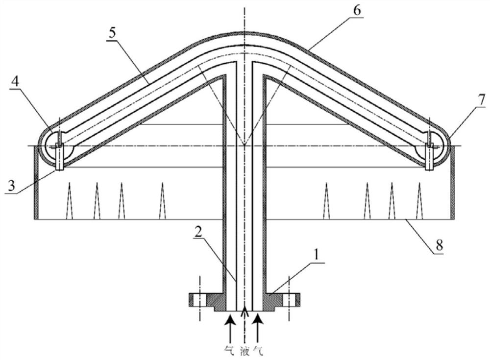
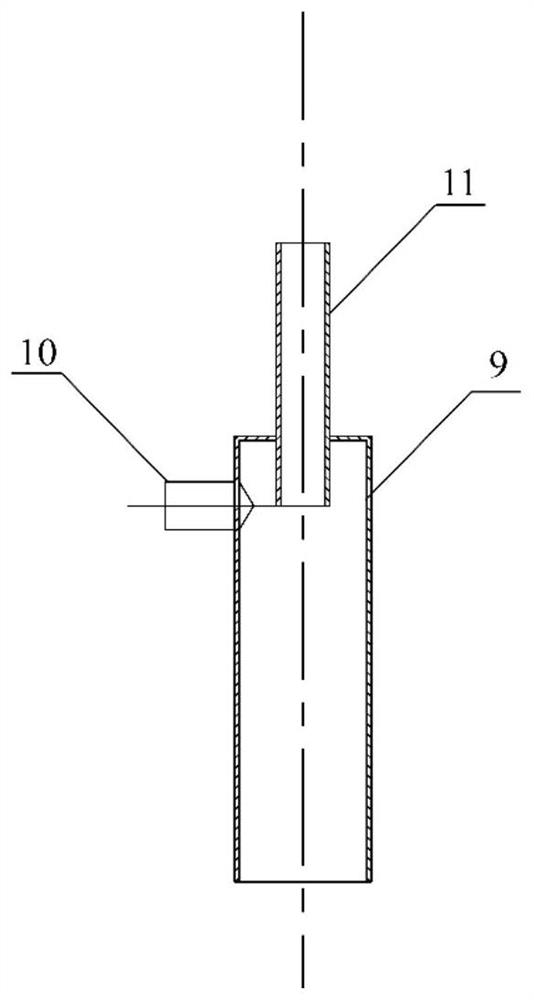
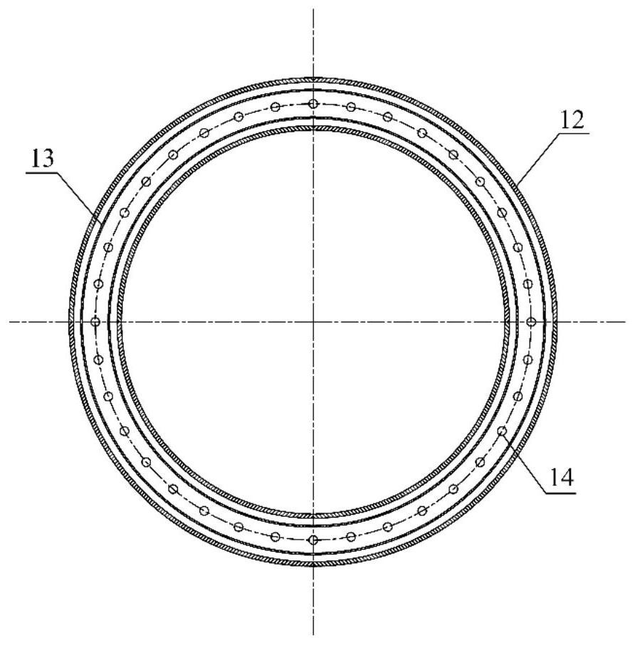
[0034] The disclosure provides a swirl self-priming distributor for an ebullated bed reactor, including: a gas inlet pipe, a liquid inlet pipe, a swirl self-suction nozzle, a liquid annular distribution pipe, a gas annular distribution pipe, a liquid branch pipe, a gas Branch pipe and skirt-like broken flow plate. The specific working principle is: the gas-liquid two-phase enters from the bottom inlet separately, the liquid phase goes through the inner pipe, the gas phase goes through the annulus between the outer pipe and the inner pipe, the gas-liquid two-phase enters through the inlet pipe and is distributed to t...


PUM


Abstract

The disclosure provides a cyclone self-priming distributor for an ebullated bed reactor, comprising: a gas inlet pipe (1) and a liquid inlet pipe (2) placed at the bottom; respectively connected to the gas inlet pipe (1) and the liquid inlet pipe (2) connected gas branch pipe (6) and liquid branch pipe (5); gas ring distribution pipe (7) and liquid ring distribution pipe (4) connected with gas branch pipe (6) and liquid branch pipe (5) respectively ); a swirl self-priming nozzle (3) placed at the bottom of the liquid annular distribution pipe (4); and a skirt-shaped broken flow plate (8) placed outside the distributor.

Description

technical field [0001] The present disclosure relates to a distributor for an ebullating bed reactor, in particular to a swirl self-priming distributor for an ebullating bed reactor. Background technique [0002] In the ebullating bed reactor, under the same liquid phase gas holdup, the smaller the bubble diameter, the larger the gas-liquid interface area, and the faster the reaction rate, the more conducive to improving the reaction rate and reaction effect. At the same time, the smaller the bubbles, the longer the residence time in the reactor, which increases the mass transfer rate between phases and further increases the conversion rate. Therefore, on the basis of uniform distribution, the sparger is more concerned about how to generate smaller bubbles, how to increase operating flexibility, and how to improve mass transfer efficiency. [0003] Chinese patent CN200945431Y introduces a new type of fluid distributor, which uses a combination of a fluid main pipe and a sho...

Claims


Application Information

Patent Timeline
Patent Type & Authority Patents(China)
IPC IPC(8): B01J8/18
CPCB01J8/1818B01J2208/00929
Inventor 常玉龙李剑平汪华林徐磊王璐唐子腾
Owner SHANGHAI HUACHANG ENVIRONMENT PROTECTION
Learn More