

Hydraulic infinitely-variable speed transmission device
A technology of hydraulic stepless transmission and transmission, which is applied in transmission control, components with teeth, belts/chains/gears, etc. It can solve the problems of high manufacturing precision of hydraulic components, narrow high-efficiency range, and low transmission efficiency. , to achieve the effect of improving work reliability, improving transmission efficiency and reliable connection
- Summary
- Abstract
- Description
- Claims
- Application Information
AI Technical Summary
Problems solved by technology
Method used
Image

Examples
Embodiment 1
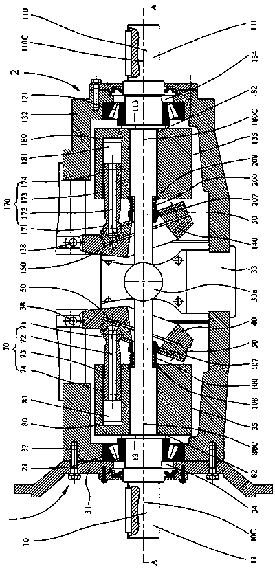
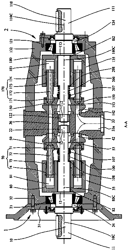
[0045] like Figure 1-9 Shown is one of the embodiments of the hydraulic continuously variable transmission device of the present invention. In the preferred embodiment shown, the hydraulic continuously variable transmission device includes a sliding plate axial piston pump 1, a The disc axial piston pump 1 is coaxially arranged with the sliding disc axial piston motor 2 and the end seat 33 sandwiched between the sliding disc axial piston pump 1 and the sliding disc axial piston motor 2 , the sliding plate axial piston pump 1 and the sliding plate axial piston motor 2 are through-shaft structures, and the sliding plate axial piston pump 1 and the sliding plate axial piston motor 2 are connected by bolts The end seat 33 is fixed to form a three-body structure.
[0046] For the sliding plate type axial piston pump 1, it includes a distribution sliding plate subassembly, which includes a pump swash plate 40 and a pump sliding plate 50 supported on the pump swash plate 40. The s...
Embodiment 2
[0069] like Figure 10-16 As shown, the main difference from Embodiment 1 is that the outer peripheral portion of the sliding plate 50 / 150 is provided with a third bearing 23 / 123 for support, and the outer peripheral portion of the swash plate is provided with a support stop portion 41a / 141a. A third bearing 23 / 123 is interposed between the inner sides of the support stop portions 41a / 141a, and the sliding plate 50 / 150 is supported on the third bearing 23 / 123 in a radially constrained state. The third bearing 23 / 123 may be set to include but not limited to one of a radial thrust ball bearing, a needle roller bearing, a cylindrical roller bearing, a tapered roller bearing, and a radial ball bearing.
[0070] During the operation of the hydraulic continuously variable transmission device, the plunger 70 / 170 in the high-pressure area is subjected to the high-pressure oil pressure of the plunger hole 81 / 181 of the cylinder body, and exerts a close pressure on the sliding plate 50 / ...
Embodiment 3
[0078] like Figure 13 As shown, the main difference from other embodiments is that a flow distribution plate 90 / 190 is sandwiched between the sliding plate 50 / 150 and the swash plate 40 / 140 in the sliding plate pair, and the static pressure bearing surface 51 / 151 is supported on the flow distribution On the plate 90 / 190 and maintain a sliding fit with the distribution plate 90 / 190, the flow plate is fixed on the swash plate by means of pins or the like. The advantage of interposing the flow distribution plate 90 / 190 between the sliding plate 50 / 150 and the swash plate 40 / 140 is that it is easier and less expensive to replace the flow distribution plate later than to replace the swash plate.
PUM
 Abstract
Description
Claims
Application Information