A thermoelectric two-field in-situ atmosphere test system under an optical microscope

An optical microscope and testing system technology, which is applied in the direction of material analysis, measuring devices, and scientific instruments through optical means, can solve problems such as high requirements, high technical requirements for personnel, and expensive in-situ electrothermal performance characterization analysis equipment, etc., to reduce The effect of production cost, low risk of experiment, and improvement of experiment efficiency and popularization rate

Active Publication Date: 2021-07-27
PEKING UNIV +1
View PDF10 Cites 0 Cited by
  • Summary
  • Abstract
  • Description
  • Claims
  • Application Information

AI Technical Summary

Problems solved by technology

[0006] In order to solve the technical problems of the existing in-situ electrothermal performance characterization and analysis equipment, which are expensive, demanding, and technically demanding, the present invention provides a thermoelectric two-field in-situ atmosphere testing system under an optical microscope, which uses an optical microscope-based workstation and sample stage And the supporting gas system, the clever design of the in-line probe with the help of the elastic probe and the in-situ chip electrode self-adaptive close contact technical scheme, realized the automatic sealing of the probe and the electrode in the in-situ chip performance test, greatly reducing the test cost, and easy to operate

Method used


Image

  • A thermoelectric two-field in-situ atmosphere test system under an optical microscope
  • A thermoelectric two-field in-situ atmosphere test system under an optical microscope
  • A thermoelectric two-field in-situ atmosphere test system under an optical microscope

Examples


Embodiment 1

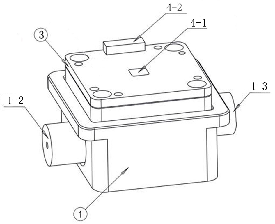
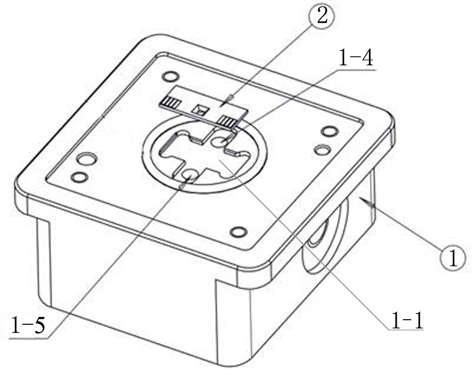
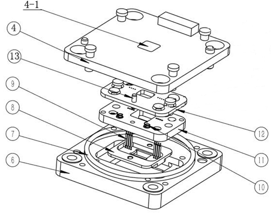
[0030]A pyroelectric two-field in-situ atmosphere testing system under an optical microscope includes an optical microscope, an electrical workstation, a sample stage connected to the electrical workstation, and a gas path system that provides an atmosphere ring mirror for the sample stage chamber. The sample stage is used to carry the sample and install it under the optical microscope for in-situ atmosphere test; the air circuit system provides the atmosphere ring mirror for the chamber of the sample stage; the electrical workstation can provide power, voltage and charge and discharge operations for the test, etc., the electrical workstation The front end is connected to the computer through a network cable, and the back end is connected to the sample stage through a corresponding electrical interface. As a key technology, the sample platform includes an integrated circuit test platform 3 and a chip mounting platform assembly 1 arranged below it and equipped with an in-situ ch...


PUM

PropertyMeasurementUnit
widthaaaaaaaaaa
currentaaaaaaaaaa
electrical resistanceaaaaaaaaaa

Abstract

The invention provides a thermoelectric two-field in-situ atmosphere test system under an optical microscope. The technical solution adopted is a thermoelectric two-field in-situ atmosphere test system under an optical microscope, which includes an optical microscope, an electrical workstation, and a sample stage connected to the electrical workstation. And the gas path system that provides the atmosphere ring mirror for the sample stage chamber, the key is that the sample stage includes an integrated circuit test bench and a chip mounting stage assembly arranged below it and is equipped with an in-situ chip, and the integrated circuit test bench includes a base 1. The probe sealing assembly and the circuit board installed on the base and the probe with the elastic probe limited in the probe sealing assembly. When the circuit board is pressed down, a self-sealing structure is formed between the probe and the electrode of the in-situ chip. The beneficial effect is that the system can complete various types of experiments such as in-situ gas heating, vacuum heating, and electrical experiments under an optical microscope, providing a basis for in-situ transmission experiments, and the operation is simple; the risk of the experiment is low, and the cost is low.

Description

technical field [0001] The invention relates to the technical field of in-situ electrothermal performance characterization equipment, in particular to a thermoelectric two-field in-situ atmosphere test system under an optical microscope. Background technique [0002] In-situ, real-time, and dynamic research on the thermoelectric and phase transition properties of materials can reflect many physical properties of materials and devices, which is conducive to promoting the design and performance optimization of materials, and greatly improving the research and development efficiency of new materials. Further improve the utilization rate of functional materials and promote the upgrading and transformation of the existing energy industry structure. The in-situ transmission electron microscope technology is to disperse the sample on the in-situ chip, and apply the transmission electron microscope to observe and study the material property-structure relationship and its dynamic cha...

Claims


Application Information

Patent Timeline
Patent Type & Authority Patents(China)
IPC IPC(8): G01N21/84G01N21/01
CPCG01N21/01G01N21/84G01N2021/0112
Inventor 鞠晶魏江涛王楠舒贾云玲蒿旭阳惠艳雨
Owner PEKING UNIV
Why Eureka
Try Eureka