
Building steel pipe cutting device

A technology of cutting device and steel pipe, applied in the direction of pipe shearing device, shearing device, accessory device of shearing machine, etc., can solve the problems of difficult grinding and cutting debris splashing, etc., and achieve the effect of easy grinding operation and restraining splashing.

Active Publication Date: 2019-08-02
江苏冰溶重型机械有限公司
View PDF7 Cites 5 Cited by
  • Summary
  • Abstract
  • Description
  • Claims
  • Application Information

AI Technical Summary

Problems solved by technology

Existing steel pipe cutting machines usually cut from the outside of the steel pipe. This operation requires the thickness of the cutting piece to be greater than the diameter of the steel pipe or to rotate the steel pipe for cutting. The cutting debris splashes heavily, and the burrs are mostly located on the inner surface, which is not easy to polish

Method used


Image

  • Building steel pipe cutting device
  • Building steel pipe cutting device
  • Building steel pipe cutting device

Examples


Embodiment 1

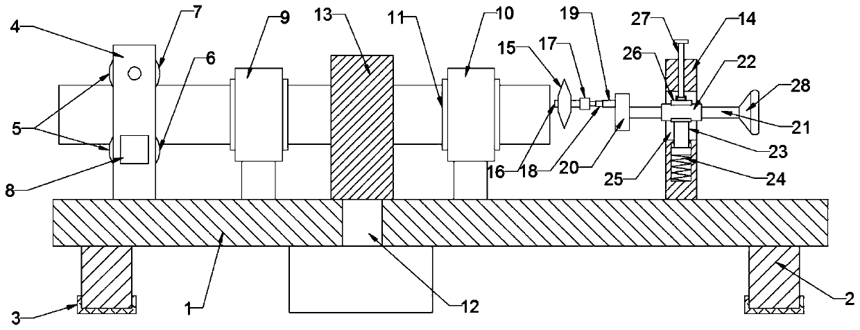
[0029] see Figure 1 to Figure 5 , a cutting device for building steel pipes, comprising a cutting machine tool 1, a feeding seat 4, a first positioning seat 9, a second positioning seat 10, a mounting frame 14 and a cutting piece 15, the bottom of the cutting machine tool 1 is equipped with a leg 2, the support The bottom of the leg 2 is provided with a shock-absorbing pad 3, which is made of rubber and fixed on the bottom of the leg 2, and is used to slow down the vibration from the cutting machine 1, which is equipped with a feeder along the same axis. Seat 4, first positioning seat 9, second positioning seat 10 and mounting frame 14,

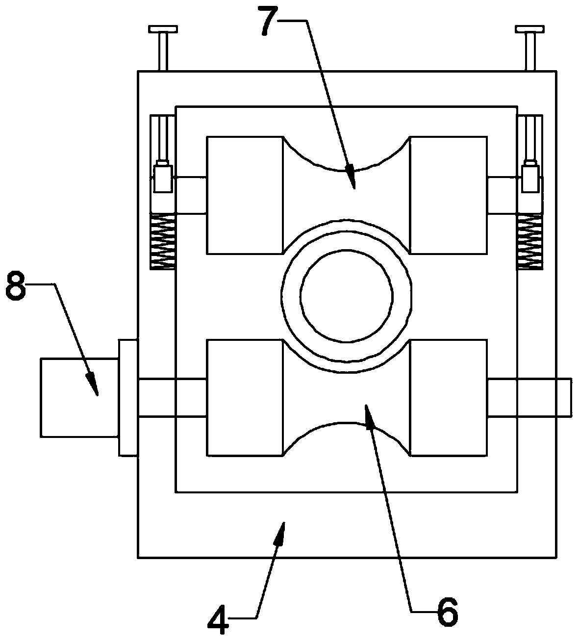
[0030] see image 3 As shown, the feeding roller 5 is installed in the feeding seat 4, and the feeding roller 5 includes a driving roller 6 and a driven roller 7, and the driving roller 6 and the driven roller 7 are arranged oppositely and are all rotatably mounted on the feeding seat 4 Inside, the driving roller 6 and the middle part of t...

Embodiment 2

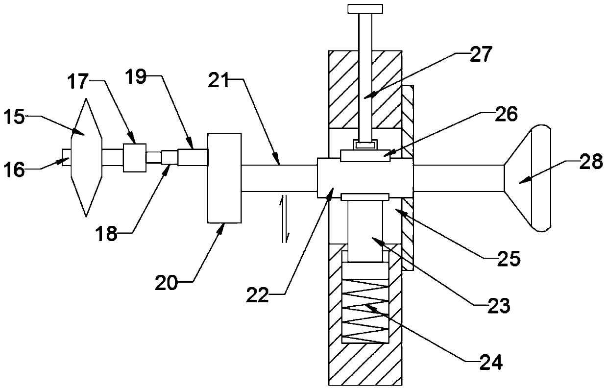
[0039] see figure 1 , Figure 3 ~ Figure 6 As shown, a construction steel pipe cutting device includes a cutting machine tool 1, a feeding seat 4, a first positioning seat 9, a second positioning seat 10, a mounting frame 14 and a cutting piece 15, and the mounting frame 14 is installed on the cutting machine tool 1 At one end, an axle sleeve 22 is installed on the mounting bracket 14, and the inner frame of the axle sleeve 22 is provided with a transmission shaft 21, and the end of the transmission shaft 21 near the second positioning seat 10 is connected to the eccentric wheel 20, and the eccentric position of the eccentric wheel 20 is equipped with a cylinder 19, and the cylinder The piston rod 18 front end of 19 is equipped with cutting motor 17, and cutting piece 15 is installed on the rotating shaft 16 of cutting motor 17, and the diameter of cutting piece 15 is less than the internal diameter of steel pipe;

[0040] Different from Embodiment 1, the end of the transmiss...


PUM


Abstract

The invention discloses a building steel pipe cutting device, and belongs to the technical field of building cutting machinery. The building steel pipe cutting device aims to solve the problems that an existing steel pipe cutting machine usually cuts from the outside of the steel pipe, the operation requires that the thickness of a cutting sheet is larger than the diameter of the steel pipe or thesteel pipe is rotated for cutting, so that chippings are seriously splashed, and burrs are mostly located on the inner side surface and are not easy to polish. The technical key points of the building steel pipe cutting device are characterized by comprising a cutting machine tool, a feeding base, a first positioning base, a second positioning base, a mounting frame and the cutting sheet; the feeding base, the first positioning base, the second positioning base and the mounting frame are sequentially arranged on the cutting machine tool along the same axis, and the cutting sheet with the diameter smaller than that of the steel pipe is arranged on the mounting frame; and a cutting motor drives the cutting sheet to rotate at a high speed, the cutting sheet is also driven by an eccentric wheel to cut the steel pipe from inside to outside, so that splashing of the chippings is effectively inhibited, moreover, the burrs of the cut steel pipe are mostly located on the outer side surface, and therefore the later grinding operation of a steel pipe cut can be more easily carried out.

Description

technical field [0001] The invention relates to the technical field of building cutting machinery, in particular to a cutting device for building steel pipes. Background technique [0002] The steel pipe is used to transfer fluid and powder, exchange heat and produce mechanical parts and containers, what's more it's a kind of economical steel. Using steel pipes to manufacture building structure grids, pillars and mechanical supports can reduce weight, save metal by 20-40%, and realize factory-like mechanized construction. The use of steel pipes to manufacture highway bridges can not only save steel and simplify construction, but also greatly reduce the area of ​​the protective layer, saving investment and maintenance costs. Especially in building construction, it has been widely used. [0003] The steel pipe cutting machine is used for cutting steel pipes, and the existing steel pipe cutting machines are generally by placing the steel pipes on the cutting table, and then c...

Claims


Application Information

Patent Timeline
Patent Type & Authority Applications(China)
IPC IPC(8): B23D21/14B23D33/02B23D35/00
CPCB23D21/14B23D33/02B23D35/005
Inventor 张山
Owner 江苏冰溶重型机械有限公司
Learn More