Check patentability & draft patents in minutes with Patsnap Eureka AI!

Wafer alignment method and pre-alignment mechanism thereof and conveying mechanical arm

A technology of robotic arms and handling machinery, which is applied in the field of IC manufacturing, can solve the problems of increasing the handling time of a single wafer, increasing the outline size of the whole machine equipment, increasing the time of wafer handling, etc., achieving simple structure, reduced size, space-saving effect

Inactive Publication Date: 2019-08-02
BEIJING U PRECISION TECH
View PDF6 Cites 4 Cited by
  • Summary
  • Abstract
  • Description
  • Claims
  • Application Information

AI Technical Summary

Problems solved by technology

[0007] However, this form requires the manipulator to reciprocate between points A, C, and B, which increases the handling time of a single wafer and affects the production capacity of the whole machine.
[0008] Moreover, in the existing pre-alignment equipment Aligner technology, the equipment has four degrees of freedom, resulting in the need for four driving devices, which increases the overall cost, and because the pre-alignment equipment exists independently of the manipulator, the complete machine equipment The outline size becomes larger, and because the pre-alignment equipment Aligner and the manipulator exist independently, the time for wafer handling increases, which is not conducive to the improvement of production line capacity

Method used


Image

  • Wafer alignment method and pre-alignment mechanism thereof and conveying mechanical arm
  • Wafer alignment method and pre-alignment mechanism thereof and conveying mechanical arm
  • Wafer alignment method and pre-alignment mechanism thereof and conveying mechanical arm

Examples


Embodiment 1

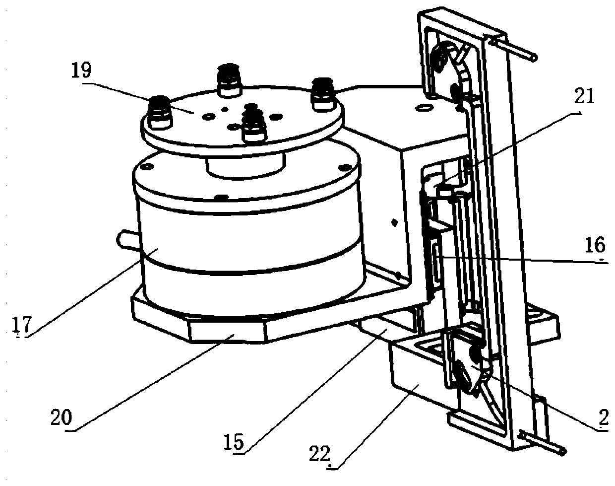
[0054] In terms of the mechanical structure of this embodiment, the wafer pre-alignment mechanism in the present invention, such as image 3 As shown, it is mainly composed of a drive motor mount 20, a direct drive motor 17, a vacuum chuck assembly 19, a drive cylinder 21, a guide rail slider mechanism 16, a connecting plate 15, a sensor assembly 2 and a sensor mounting plate 22.

[0055] In the pre-alignment mechanism of the present invention, the vacuum chuck assembly 19 used to contact the wafer is driven by the drive motor 17, and all the drive motors and the vacuum chuck assembly 19 are installed on the drive motor mount 20. The drive motor mount 20 can be driven up and down by the cylinder 21 and can be used as an auxiliary guide by means of the guide rail slider mechanism 16 . And the fixed support (connecting plate 15) can be connected with the mounting plate 4 at the bottom of the manipulator attached to it by bolts. The sensor assembly 2 is used to find the center o...

Embodiment 2

[0062] This embodiment describes a wafer handling robotic arm with pre-alignment function of the present invention, which mainly includes a set of direct drive motor (drive motor), a set of synchronous belt transmission system, and a set of guide rail slider system , a set of end effectors, a support mechanism and a set of wafer pre-alignment mechanism, wherein the wafer pre-alignment mechanism includes another set of direct drive motor (drive motor), guide rail slider mechanism, and a set of cylinder system , a wafer chuck, a sensor assembly and a drive motor mounting seat, wherein, in order to ensure the overall stability of the mechanism and the load of the guide rail slider is not overloaded, the guide rail slider mechanism can be two sets in this specific embodiment.

[0063] see Image 6 , is a schematic structural diagram of a specific implementation of the wafer handling robot arm with pre-alignment function of the present invention. Such as Image 6 As shown, the me...


PUM


Abstract

The invention provides a wafer alignment method and a pre-alignment mechanism thereof and a conveying mechanical arm, relates to a process and a device used in the field of wafer transmission, and aims at providing a wafer alignment method with simple structure, low cost and simple operation, a pre-alignment mechanism thereof and a conveying mechanical arm. The bottom of the wafer conveying mechanical arm with a pre-alignment function is mainly used. A direct drive motor is arranged to drive the whole alignment mechanism to rotate around the vertical axis. The mechanism body is a mechanical arm mechanism in which the motor drives the end actuator to perform telescopic movement through a synchronous belt, or a linear motor drives the end actuator to perform telescopic movement directly. A wafer pre-alignment mechanism is installed inside the mechanical arm, the lifting motion is driven by a cylinder and the rotating motion is driven by the direct drive motor. Therefore, the pre-alignment behavior can be performed directly after the wafer is taken by the end actuator of the mechanical arm and the wafer is taken and moved directly to the designated position for placing the wafer afterthe alignment, thereby greatly saving the time from the wafer pickup point to the alignment mechanism in the past.

Description

technical field [0001] The invention relates to the field of IC manufacturing, in particular to a method for aligning wafers for transporting wafers, a pre-alignment mechanism, and a transporting robot arm. Background technique [0002] With the development of society, the information age is getting farther and farther, the integrated circuit industry is in full swing, and the demand for peripheral related equipment is also increasing. Manipulators have also appeared in various forms. [0003] see figure 1 and 2 , due to the particularity of the wafer, in the process, on the one hand, it is necessary to use the manipulator to transport the wafer from point A to point B. In most cases, it is necessary to perform a series of alignment operations before the handling to ensure Wafer orientation to point B is consistent. At present, the pre-alignment equipment on the market is basically independent, so usually the wafer handling and alignment operations are performed by two i...

Claims


Application Information

Patent Timeline
IPC IPC(8): H01L21/66H01L21/677H01L21/68H01L21/683H01L21/687
CPCH01L21/67703H01L21/68H01L21/6838H01L21/68707H01L22/12
Inventor 朱煜张豹李健杨开明
Owner BEIJING U PRECISION TECH
Features
  • R&D
  • Intellectual Property
  • Life Sciences
  • Materials
  • Tech Scout
  • Unparalleled Data Quality
  • Higher Quality Content
  • 60% Fewer Hallucinations
Learn More