Shielded gate MOSFET device with shielding layer and preparation method thereof
A technology of shielding gate and shielding layer, which is applied in semiconductor/solid-state device manufacturing, semiconductor devices, electrical components, etc., can solve the problem of reducing device transfer capacitance, shorten the design cycle and cost, reduce switching loss, and reduce the cost of small chips. Effect
- Summary
- Abstract
- Description
- Claims
- Application Information
AI Technical Summary
Problems solved by technology
Method used
Image
Examples
Embodiment 1
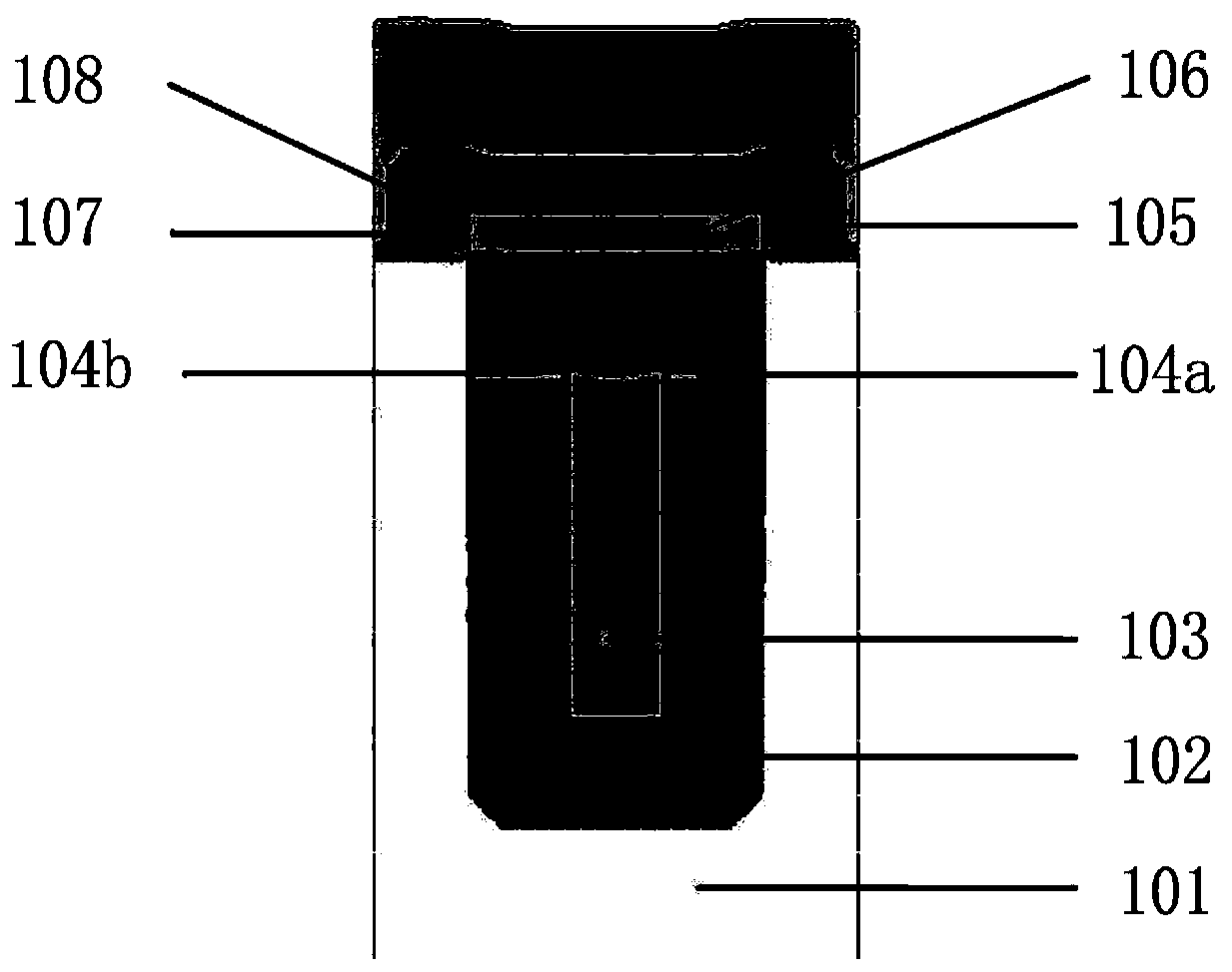
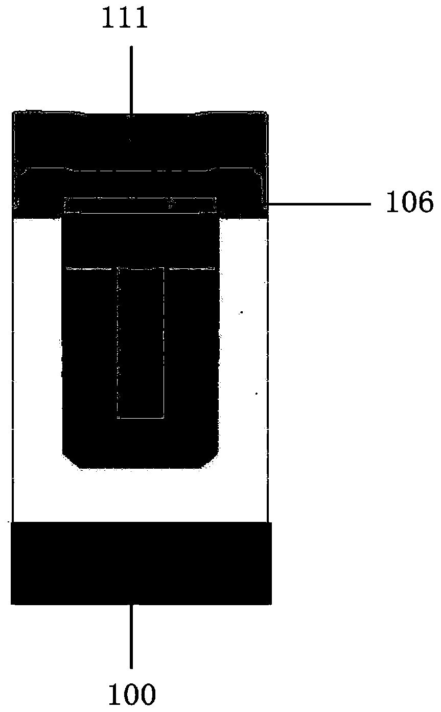
[0064] A specific embodiment of the present invention discloses a shielded gate MOSFET device with a shielding layer, such as figure 1 As shown, its conduction region includes a plurality of periodically arranged primitive cells, and the gate structure of each of the primitive cells includes a trench, a main shield electrode 103, two sub shield electrodes 104a, 104b and a trench gate electrode 106. The number of primitive cells is determined by specific design requirements, which is not limited in this embodiment.
[0065] The trench is disposed in the epitaxial layer 101 of the first conductivity type on the semiconductor substrate.
[0066] The main shield electrode 103, the two sub-shield electrodes 104a, 104b and the trench gate electrode 106 are all disposed in the trenches. The trench gate electrode 106 is arranged on the top of the trench, the main and secondary shield electrodes are arranged below the trench gate electrode 106 , and the two sub-shield electrodes 104 ...
Embodiment 2
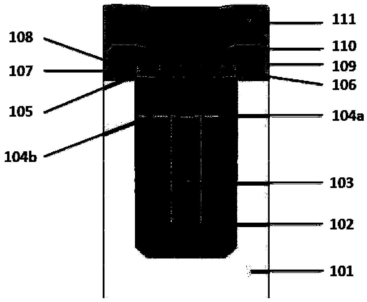
[0072] Optimized on the basis of the shielded gate MOSFET device with shielding layer described in Example 1, such as image 3 As shown, the main shielding electrode 103 is arranged vertically, and the secondary shielding electrodes 104a, 104b and the trench gate electrode 106 are arranged horizontally.
[0073] In order to improve the manufacturing efficiency of the process, the main shielding electrode 103 and the trench gate electrode 106 may be arranged axially symmetrically along the central axis of the trench, so that the process is easy to implement and the manufacturing cost is reduced.
[0074] Preferably, the thickness of each of the secondary shielding electrodes 104a, 104b is 3%-5% of the thickness of the main shielding electrode 103, and the width thereof is 95%-99% of the width of the main shielding electrode 103, which is the same as the thickness of the main shielding electrode 103. The interval between the main shield electrodes 103 is 3% to 5% of the width of...
Embodiment 3
[0086] Another specific embodiment of the present invention discloses a method for preparing the shielded gate MOSFET device with a shielding layer described in Embodiment 1, such as Figure 5 As shown, the method includes the following steps:
[0087] S1. depositing an epitaxial layer 101 of a first conductivity type on a semiconductor substrate, and preparing a trench on the epitaxial layer;
[0088] S2. The main shield electrode 103, the two sub-shield electrodes 104a, 104b, and the trench gate electrode 106 are sequentially prepared inside the trench to form a channel region 107 and a drift region; wherein, the trench gate electrode 106 is arranged in At the top of the trench, the main and sub-shielding electrodes 104a, 104b are arranged below the trench gate electrode 106, and the two sub-shielding electrodes 104a, 104b are symmetrically arranged on both sides of the top of the main shielding electrode 103; the channel region 107 It is arranged on both sides of the trenc...
PUM
| Property | Measurement | Unit |
|---|---|---|
| Thickness | aaaaa | aaaaa |
| Width | aaaaa | aaaaa |
| Thickness | aaaaa | aaaaa |
Abstract
Description
Claims
Application Information
 - R&D Engineer
- R&D Manager
- IP Professional
- Industry Leading Data Capabilities
- Powerful AI technology
- Patent DNA Extraction
Browse by: Latest US Patents, China's latest patents, Technical Efficacy Thesaurus, Application Domain, Technology Topic, Popular Technical Reports.
© 2024 PatSnap. All rights reserved.Legal|Privacy policy|Modern Slavery Act Transparency Statement|Sitemap|About US| Contact US: help@patsnap.com


