A thin strip continuous casting strip steel cooling mechanism and cooling method thereof

A cooling mechanism and strip steel technology, applied in the field of thin strip continuous casting, can solve the problems of hindering the gasification of cooling water, large cooling speed adjustment range, complex equipment, etc., to achieve cooling uniformity, ensure cooling uniformity, uniformity The effect of the cooling effect

Active Publication Date: 2021-11-23
BAOSHAN IRON & STEEL CO LTD +1
View PDF17 Cites 0 Cited by
  • Summary
  • Abstract
  • Description
  • Claims
  • Application Information

AI Technical Summary

Problems solved by technology

It uses the principle of water atomization to spray water onto the surface of the steel plate in the form of mist, with uniform cooling and a wide range of cooling speed adjustment. The disadvantage is that the equipment is complex, the requirements for air and water are strict, the factory building is foggy, and the equipment is easy to be corroded; it is suitable for from Wide range of cooling capacity from air cooling to strong water cooling, especially suitable for continuous casting secondary cooling
[0010] Because different strip steel cooling methods have different cooling mechanisms, air mist cooling relies on compressed air to break the water flow into droplets, and the liquid droplets collide with the hot strip to quickly absorb heat and gasify, thereby taking away a large amount of heat and achieving the maximum efficiency of strip steel cooling. Purpose; but when the flow rate of the air mist cooling water is large, there is still a residual water film layer on the strip steel, and there is an air film layer between the water film layer and the hot strip, and this layer of air film hinders the gasification of the cooling water. Reactive to heat transport

Method used


Image

  • A thin strip continuous casting strip steel cooling mechanism and cooling method thereof
  • A thin strip continuous casting strip steel cooling mechanism and cooling method thereof
  • A thin strip continuous casting strip steel cooling mechanism and cooling method thereof

Examples


Embodiment Construction

[0053] The present invention will be described in further detail below in conjunction with the accompanying drawings and specific embodiments, but not as a limitation of the present invention.

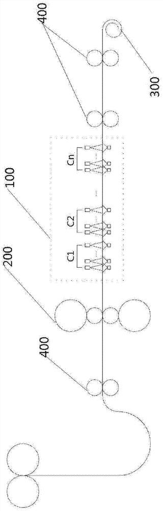
[0054] Such as figure 1 As shown, it is a schematic diagram of the position of the thin strip continuous casting strip cooling mechanism according to the embodiment of the present invention, wherein the cooling mechanism 100 is arranged on the horizontal roller table at the exit of the rolling mill, and is located between the rolling mill mechanism 200 and the crimping mechanism 300, and as figure 1 As shown, between the cooling mechanism 100 and the crimping mechanism 300 and on the front side of the rolling mill mechanism 200, multiple groups of pinch rollers 400 can also be arranged to clamp and transport the steel strip and form a certain tension; wherein, the rolling mill mechanism 200 It is used to control the shape and thickness of the steel strip, and the crimping mechanism 300...


PUM


Abstract

A thin strip continuous casting strip steel cooling mechanism, which is provided with a plurality of cooling groups (C1, C2, ..., Cn), each cooling group includes at least one cooling unit (1), each cooling group The cooling method of the cooling unit is at least one of air mist cooling, laminar flow cooling, and jet cooling; the cooling units are respectively located on the upper side and the lower side of the roller table, and include a header main road (2 ) and at least two header branches (3) connected to the header main road, a plurality of nozzles (4) are arranged on the header branch, and an on-off switch ( 5), the water pipe and the air pipe are also provided with an opening control valve (6) for controlling the flow of gas and liquid in the cooling unit. The cooling mechanism realizes the control of the cooling speed of the steel strip, and has the effect of uniformly cooling the steel strip. It also includes a cooling method for the thin strip continuous casting strip steel cooling mechanism.

Description

technical field [0001] The invention relates to the technical field of thin strip continuous casting, in particular to a thin strip continuous casting strip steel cooling mechanism and a cooling method of the cooling mechanism. Background technique [0002] At present, thin strip continuous casting is based on different steel casting requirements. The thin strip continuous casting process requires equipment to meet different cooling rates and coiling temperature control to meet the production needs of different steel grades. [0003] At present, the controlled cooling methods of strip steel mainly include laminar flow cooling, pressure spray cooling, spray cooling, water curtain cooling, direct quenching and gas mist cooling. [0004] Among them, the laminar flow cooling is to cool the surface of the steel plate through the columnar water flow, and the water flow maintains a laminar flow state, which can obtain a strong cooling capacity; the disadvantage is that the cooling ...

Claims


Application Information

Patent Timeline
Patent Type & Authority Patents(China)
IPC IPC(8): B22D11/124
CPCB22D11/124
Inventor 张宇军徐乐江叶长宏方园王星冈安晋平堀井健治
Owner BAOSHAN IRON & STEEL CO LTD
Why Eureka
Try Eureka