Threaded pile drill pipe for reinforcing local silt layer and pile forming method thereof

A technology of silt layer and threaded piles, which is applied in the field of civil engineering pile forming technology, can solve the problems of loose concrete pile density, difficult control of pump pressure, and unavailable threaded piles, etc., to achieve reduced attenuation, controllable operation, and expanded spraying The effect of radius

Active Publication Date: 2020-08-21
HUAIYIN INSTITUTE OF TECHNOLOGY
View PDF5 Cites 0 Cited by
  • Summary
  • Abstract
  • Description
  • Claims
  • Application Information

AI Technical Summary

Problems solved by technology

[0004] The foundation soil belongs to the earth's surface rock and soil, which is formed through complex physical, chemical and biological processes in nature. The geological survey results generally show a layered distribution. The resistance of the pile tip and the side friction of the pile body are used as the bearing capacity of the pile foundation. If there is a muddy soft soil layer with a high water content in the middle, not only will the concrete at the edge of the drill pipe be segregated and dispersed into the silt during the construction stage when the fluid concrete is pumped. In this part, the density of the concrete pile body is loose, and the pump pressure is difficult to control. The current mixing pile uses mud retaining wall or immersed tube to prevent dispersion, but these two measures cannot be taken for threaded piles; and this part has relatively high water content. The high silt soft soil layer has little effect on the side friction resistance of the formed concrete pile, even if the pile side is threaded, it cannot provide a good contribution to the load bearing of the pile

Method used


Image

  • Threaded pile drill pipe for reinforcing local silt layer and pile forming method thereof
  • Threaded pile drill pipe for reinforcing local silt layer and pile forming method thereof
  • Threaded pile drill pipe for reinforcing local silt layer and pile forming method thereof

Examples


Embodiment Construction

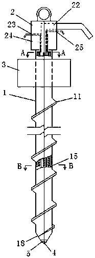
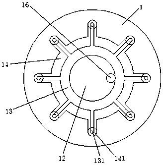
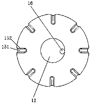
[0033] Such as Figure 1 to Figure 6As shown, a threaded pile drill pipe for reinforcing local silt layers according to the present invention includes a drill pipe 1, a rotary jet drilling tool diverter 2, and a power device 3. The surface of the drill pipe 1 has threads 11, and the inner shaft center Up and down through the perfusion chamber 12, the top of the drill pipe 1 is rotatably connected to the diverter 2 of the rotary jet drilling tool, the upper part of the drill pipe 1 is sleeved with the power unit 3, and the upper part of the drill pipe 1 is provided with a powder ring coaxial with the perfusion chamber 12 Cavity 13 and air ring cavity 14, and the rotary grouting drilling tool splitter 2 is equipped with a corresponding drill pipe perfusion cavity, powder ring cavity, and air ring cavity channel (that is, perfusion cavity channel 22, powder ring cavity channel 23, and air ring cavity channel 24 ), the outer entrances of each channel are respectively used to conne...


PUM


Abstract

The invention discloses a threaded pile drill pipe for reinforcing a local mud layer and a threaded pile forming method for a foundation thread pile containing a mud layer. Spray drilling tool splitter, the upper part of the drill pipe is socketed with the power unit, the inner upper part of the drill pipe is provided with a powder ring cavity and an air ring cavity coaxial with the filling cavity, and the rotary jet drilling tool splitter is equipped with a corresponding connected drill pipe The passages of the pouring chamber, the powder ring chamber and the air ring chamber are respectively used to connect the high-pressure fluid concrete pump, the high-pressure powder pump, and the high-pressure air pump at the outer entrances of each passage. The radial nozzle, the end face of the nozzle is a concentric central powder injection hole and an outer ring air injection hole, the powder injection hole is connected with the powder ring cavity, and the air injection hole is connected with the air ring cavity. Use this special drill pipe to reinforce the silt sandwich layer when forming a hole to form a threaded pile with an overall structure.

Description

technical field [0001] The invention relates to the technical field of civil engineering pile forming technology, more specifically, it relates to a threaded pile drill pipe for reinforcing a local mud layer and a method for forming a foundation threaded pile containing the mud layer. Background technique [0002] The threaded pile and its pile-forming method are new pile types based on the long helical drilled pile and the Japanese steel drill-dimensional full-threaded prefabricated pile, which changes the interaction mode between the pile and the soil, and the interface between the pile and the soil A mechanical occlusion is formed, and the principle of "screws are stronger than nails" in common sense is applied to pile construction, so that its stronger characteristics can be realized. The surface of the threaded pile is threaded, which is formed by rotating and extruding the surrounding soil through a special drill pipe with screw teeth. No or a little soil is discharged...

Claims


Application Information

Patent Timeline
Patent Type & Authority Patents(China)
IPC IPC(8): E21B17/22E21B17/18E21B47/06E02D5/56E02D5/36E02D15/04
CPCE02D5/36E02D5/56E02D15/04E02D2250/0023E21B17/18E21B17/22E21B47/06
Inventor 陈亚东陆凡邱泉蔡江东孙华圣曹茂柏
Owner HUAIYIN INSTITUTE OF TECHNOLOGY
Why Eureka
Try Eureka