Thin size high-strength steel for engineering machinery and strip shape control method

A technology for construction machinery and high-strength steel plates, applied in the field of high-strength steel manufacturing, can solve the problems of high strength and elongation margin, high content of precious metal Mo, and push up production costs, etc., to achieve a cost-effective effect

Active Publication Date: 2019-08-09
武汉钢铁有限公司
View PDF9 Cites 7 Cited by
  • Summary
  • Abstract
  • Description
  • Claims
  • Application Information

AI Technical Summary

Problems solved by technology
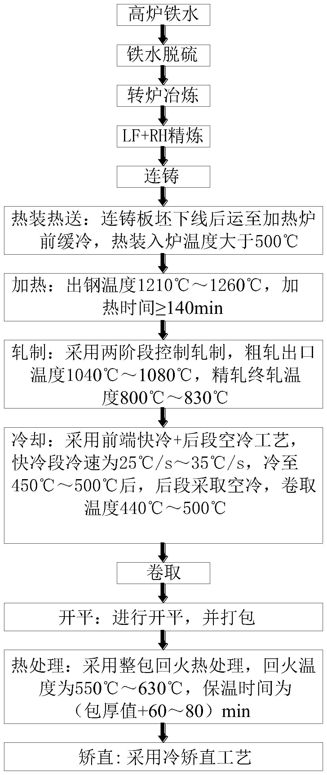
Its strength and elongation have large margins, good impact toughness, and low loss of strength after welding, but the means to improve the final shape of the plate mainly rely on tempering heat treatment to eliminate stress, without considering that the release of stress after tempering may further deteriorate the shape of the plate Possibility, the quality of the plate shape may not be stable enough. In addition, its precious metal Mo content is high, which pushes up the production cost, and for steel plates above 8.5mm, it cannot be produced
[0006] Publication No. CN101670372B invention patent discloses a method for eliminating shape defects of hot-rolled high-strength steel plates. The combination of temper rolling, bell annealing and roller straightening processes is introduced into the specification range of thickness 3-18.4mm×width 900-1800mm, yield The production and processing process of hot-rolled high-strength steel coils with strength ≥ 600MPa eliminates the internal stress of hot-rolled high-strength steel, significantly improves the shape quality, and enables users to obtain good shape stability, which can meet users' requirements for flatness less than or equal to The strict requirement of 2mm / m, but there is a certain contradiction between the internal stress relief uniformity and strength of the bell-type annealed steel coil, and the requirements for temperature control are relatively high. The impact is critical, the patent does not mention the original plate (coil) control means

Method used


Image

  • Thin size high-strength steel for engineering machinery and strip shape control method
  • Thin size high-strength steel for engineering machinery and strip shape control method
  • Thin size high-strength steel for engineering machinery and strip shape control method

Examples


Embodiment 1~3

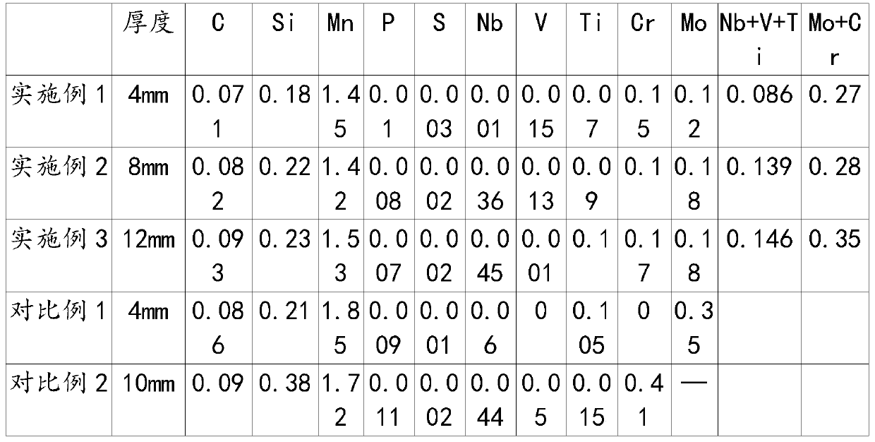
[0057] Examples 1-3, a high-strength steel for thin-gauge construction machinery, the specific chemical components and their weight percentages are shown in Table 1; Comparative Examples 1-2, the chemical components and their weight percentages are also shown in Table 1:

[0058] Table 1

[0059]

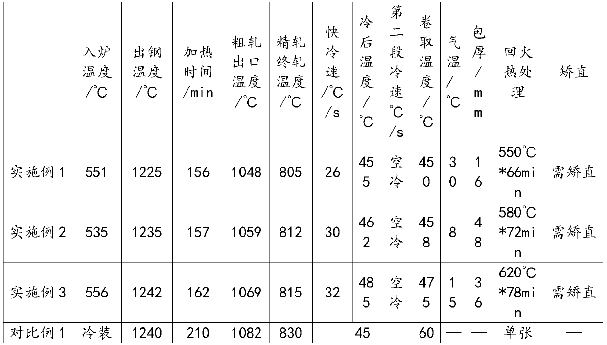
[0060] The concrete process data of production process feature among embodiment 1-3 and comparative example 1-2 is shown in Table 2:

[0061] Table 2

[0062]

[0063]

[0064] According to national standards GB / T228 and GB / T231, the properties of the thin-gauge high-strength engineering machinery steels described in Examples 1-3 and Comparative Examples 1-2 are shown in Table 3.

[0065] table 3

[0066]

[0067]

[0068] It can be seen that under the three processes of the example, the yield strength is above 690MPa, the tensile strength is above 790MPa, the A50 is above 21%, the low temperature toughness at -20°C is excellent, the transverse and longitudinal cold...


PUM

PropertyMeasurementUnit
yield strengthaaaaaaaaaa
tensile strengthaaaaaaaaaa
thicknessaaaaaaaaaa

Abstract

The invention relates to thin size high-strength steel for engineering machinery. The steel is prepared from the following components in percentage by mass: 0.07%-0.10% of C, 0.15%-0.30% of Si, 1.2%-1.6% of Mn, less than or equal to 0.012% of P, less than or equal to 0.003% of S, 0%-0.08% of Nb, 0%-0.07% of V, 0.06%-0.13% of Ti, 0.1%-0.2% of Cr, 0.1%-0.2% of Mo, 0.08%-0.15% of Nb+V+Ti, 0.25%-0.35%of Mo+Cr, and the balance Fe and impurities. The the strip shape control method is characterized in comprising blast furnace molten iron, molten iron desulfurization, converter smelting, LF+RH refining, continuous casting, hot charging and hot conveying, heating, rolling, cooling, coiling, flattening, tempering heat treatment and straightening process. According to the steel, the yield strength is greater than 690 MPa, the tensile strength is greater than 785 MPa, and the impact work at minus 20 DEG C is greater than 100 J.

Description

technical field [0001] The invention relates to the field of high-strength steel manufacturing, in particular to a high-strength steel for thin-gauge construction machinery and a shape control method. Background technique [0002] Thin-gauge high-strength steel for construction machinery is widely used in the manufacture of cranes, aerial work vehicle booms and other equipment. It requires high safety performance. In addition to reaching a certain strength level, it also requires excellent shape quality. The quality will make it difficult to weld after cold bending or the welding stress is too large. Once defects such as welding cracks occur during use, there is a high probability of causing safety accidents and the impact is bad. [0003] In order to obtain excellent shape quality, some steel mills use slow cooling of hot-rolled coils or annealing in bell annealing furnaces for flattening, or use multiple times of heat straightening, all of which have certain effects, but t...

Claims


Application Information

Patent Timeline
Patent Type & Authority Applications(China)
IPC IPC(8): C21D1/18C21D6/00C21D8/02C21D9/00C22C33/04C22C38/02C22C38/04C22C38/22C22C38/24C22C38/26C22C38/28C22C38/38
CPCC21D1/18C21D6/002C21D6/005C21D6/008C21D8/0221C21D9/0081C22C33/04C22C38/002C22C38/02C22C38/04C22C38/22C22C38/24C22C38/26C22C38/28C22C38/38
Inventor 何亚元宋育来陆在学李利巍徐进桥杨海林张鹏武王建立王跃
Owner 武汉钢铁有限公司
Why Eureka
Try Eureka