A Quenching Device for Large Forged Fan Spindle

A large-scale forging and quenching device technology, applied in the direction of quenching devices, furnace types, furnaces, etc., can solve problems such as poor quenching, inability to improve toughness, and inability to pursue the quenching effect alone, so as to improve the quenching effect and increase the depth of the hardened layer , the effect of improving toughness

Active Publication Date: 2021-01-15
SHANDONG LAIWU JINLEI WIND POWER TECH
View PDF7 Cites 0 Cited by
  • Summary
  • Abstract
  • Description
  • Claims
  • Application Information

AI Technical Summary

Problems solved by technology

The key factor that restricts the performance index of the fan spindle is how to improve the toughness of the spindle product. According to professional analysis, poor quenching is the key factor that leads to the inab

Method used


Image

  • A Quenching Device for Large Forged Fan Spindle
  • A Quenching Device for Large Forged Fan Spindle

Examples


Example Embodiment

[0014] Example 1

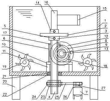
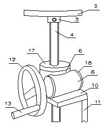
[0015] A quenching device for a fan spindle for large-scale forgings, comprising: a sample tank 1, a rotating platform 2 is arranged in the sample tank, the rotating platform is fixedly connected to a circular sleeve 3, and the circular sleeve is connected to a lifting screw 4. The round sleeve and the lifting screw are fixed by screws 5, the lifting screw is installed in the housing 6, the bottom of the lifting screw is connected to the transmission device, and the transmission device is connected to the motor 7, The housing is fixedly connected to the sub-housing 8, the sub-housing is equipped with a horizontal screw 9, the horizontal screw engages the lifting screw, and the housing is connected to the sub-housing The base plate 10, the base plate is connected to the support leg 11, the horizontal screw rod is connected to the control panel 12, the control panel is connected to the handle 13, the rotating platform is connected to the fixed sleeve 14, the f...

Example Embodiment

[0016] Example 2

[0017] A quenching device for a large-scale forging blower fan spindle described in Example 1, the housing is connected to the sealing cover 17, the auxiliary housing is connected to the auxiliary sealing cover 18, and maple leaves are arranged around the sample tank. Stirrer 19, the maple leaf stirrer is distributed around the lifting screw, the bottom of the maple leaf stirrer is fixed on the bottom of the sample tank, and the bottom of the sample tank is connected to the total support leg 20.

Example Embodiment

[0018] Example 3

[0019] In the quenching device for a fan spindle for a large forging fan described in Example 2, a through hole 21 is opened at the bottom of the sample tank, and the lifting screw passes through the through hole, and the through hole is connected to the through hole. A sealing ring 22 is installed between the lifting screws, the lifting screw is connected to the threaded sleeve 23, the threaded sleeve is fixedly connected to the pulley 24, the pulley is connected to the belt 25, and the belt is connected to the main pulley 26. The output shaft 27 of the primary pulley connected motor.


PUM


Abstract

The invention provides a large forging fan main shaft quenching device. The product comprises a sample groove, wherein a rotating platform is arranged in the sample groove; the rotating platform is fixedly connected with a round sleeve; the round sleeve is connected with a lifting screw and is fixed to the lifting screw through a screw nail; the lifting screw is mounted in a shell; the bottom of the lifting screw is connected with a transmission device; the transmission device is connected with a motor; the shell is fixedly connected with a secondary shell; a transverse screw is mounted in thesecondary shell, and is engaged with the lifting screw; the shell and the secondary shell are connected with a bottom plate; the bottom plate is connected with supporting legs; the transverse screw is connected with a control plate; the control plate is connected with a handle; the rotating platform is connected with a fixing sleeve; the fixing sleeve is connected with a main shaft and is fixed by a screw; the main shaft is connected with a sample area; a quenching main shaft is mounted in the sample area; and quenching liquid is arranged in the sample groove. The large forging fan main shaftquenching device is used for quenching a large forging fan main shaft.

Description

technical field [0001] The invention relates to a quenching device for the main shaft of a blower fan for large forgings. Background technique [0002] At present, almost all fan shafts are large-scale forgings. The heat treatment process of fan shafts is quenching and tempering (quenching + high temperature tempering). Fans have been in harsh environments for a long time. As an important component, the performance indicators of the shaft are very strict. The key factor that restricts the performance index of the fan spindle is how to improve the toughness of the spindle product. According to professional analysis, poor quenching is the key factor that leads to the inability to improve the toughness. Complete quenching and product cracking form a contradiction, which cannot be pursued in a single way. The quenching effect must be considered comprehensively to achieve a suitable node. Contents of the invention [0003] The purpose of the present invention is to provide a l...

Claims


Application Information

Patent Timeline
IPC IPC(8): C21D9/28C21D1/63
CPCC21D1/63C21D9/0062C21D9/28
Inventor 史可庆刘哲毕京华张青卢梁
Owner SHANDONG LAIWU JINLEI WIND POWER TECH
Why Eureka
Try Eureka