A nanofiber electrospinning equipment

A technology of electrospinning and nanofibers, which is applied in fiber processing, complete sets of equipment for producing artificial threads, filament generation, etc. It can solve the problems of low drying efficiency, poor drying uniformity, and large volume, and achieve the overall structural volume Small size, smooth collection process and high collection efficiency

Active Publication Date: 2021-07-30
HIDETAKA NANO TECH CO LTD
View PDF13 Cites 0 Cited by
  • Summary
  • Abstract
  • Description
  • Claims
  • Application Information

AI Technical Summary

Problems solved by technology

There are the following technical defects in this preparation process: (1) The nanofibers produced by the electrospinning equipment naturally descend to the collection base by gravity, the collection base is in the shape of a flat disc, and the fibers are piled up on the collection base in a disorderly manner , it is very easy to cause the mixing of the fiber filaments, and the winding fluency of the nanofiber filaments is low
(2) The supporting drying equipment in the electrospinning equipment mostly adopts a single heat conduction form of heat convection or heat radiation to dry the fiber filaments, and the drying uniformity is poor; The internal volume of the drying device is not fully utilized, the drying efficiency is low, and it is not suitable for drying nanofiber tows with small diameters
(4) For electrospinning transportation, due to the small diameter of the nanofibers, the conventional rollers cannot fix the nanofibers, and the fibers and the rollers are prone to slipping during the transportation process, which affects the smoothness of the rollers.
(5) In order to protect the mechanical strength of nanofibers during transportation, and prevent the fibers from being pulled tightly or loosely due to factors such as friction during long-distance transportation, resulting in fiber breakage or mixing, now It is impossible to adjust the tension state of the fiber in some roller structures

Method used


Image

  • A nanofiber electrospinning equipment
  • A nanofiber electrospinning equipment
  • A nanofiber electrospinning equipment

Examples


Embodiment Construction

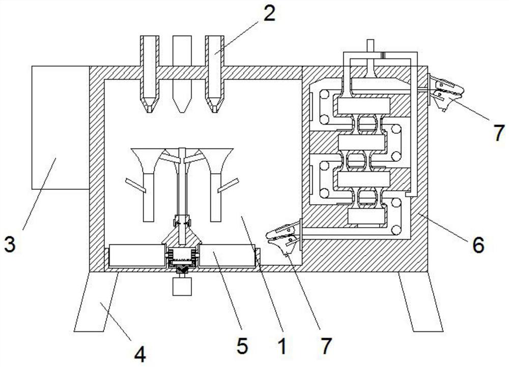
[0060] In order to make the technical solution of the present invention clearer, the present invention will be further described below in conjunction with the accompanying drawings. Any solution obtained by equivalent replacement and conventional reasoning of the technical features of the technical solution of the present invention falls within the protection scope of the present invention. The fixed connection, fixed arrangement, and fixed structure mentioned in this embodiment are known technologies known to those skilled in the art, such as gluing, welding, screw connection, bolt and nut connection, and riveting. The collection motor mentioned in the present invention is a common three-phase asynchronous AC motor, and the horizontal heating tube, the vertical heating tube and the side heating tube are nanofiber heating tubes, and the products are all products that can be purchased directly in the market. The structural principle is as follows: Known technologies well known t...


PUM

PropertyMeasurementUnit
diameteraaaaaaaaaa

Abstract

A nanofiber electrospinning equipment, comprising a spinning shell, a spinning head, a power supply box, a shell foot, a collecting device, a drying device, and a conveying roller; the spinning head is arranged on the spinning shell The top of the body; the power supply box is arranged on the outer wall of the spinning casing, and the power supply box is electrically connected to the spinning head through a wire; the casing feet are arranged on the bottom surface of the casing; the collecting The device is arranged on one side of the bottom end of the spinning shell, the drying device is set on one side of the spinning shell; the conveying roller is set on the inlet of the drying box and the drying box body exit. The present invention improves the fluency and stability of the system preparation by designing the collecting device and the conveying roller, and at the same time designs the drying device to make the product have stronger performance.

Description

technical field [0001] The invention belongs to the field of nanofiber production equipment, in particular to nanofiber electrostatic spinning equipment. Background technique [0002] Nanomaterials refer to materials with at least one dimension in nanometer size (0.1-100 nm) or composed of them as basic units in three-dimensional space, which is approximately equivalent to the scale of 10-100 atoms closely arranged together. In nanomaterials, nanofibers refer to ultrafine fibers with a fiber diameter of less than 1000 nanometers. There are many methods for fabricating nanofibers, such as stretching method, template synthesis, self-assembly, microphase separation, electrospinning, etc. Among them, the electrospinning method is widely used due to its advantages of simple operation, wide application range and relatively high production efficiency. [0003] Electrospinning is a special fiber manufacturing process in which a polymer solution or melt is jet-spun in a strong elec...

Claims


Application Information

Patent Timeline
Patent Type & Authority Patents(China)
IPC IPC(8): D01D5/00D01D10/06D01D11/00D01D13/00
CPCD01D5/0061D01D5/0069D01D5/0076D01D10/06D01D11/00D01D13/00
Inventor 崔建中
Owner HIDETAKA NANO TECH CO LTD
Why Eureka
Try Eureka