Vehicle air conditioner and heat pump integrated system

A vehicle air conditioner and heat pump technology, which is applied to vehicle parts, refrigeration and liquefaction, and air treatment equipment, etc., can solve the problems of large filling capacity, air leakage and heat leakage, and occupy a lot of space, so as to reduce the risk of safe driving accidents , The effect of reducing the pressure on the high pressure side and uniform temperature distribution

Inactive Publication Date: 2019-08-09
上海银轮热交换系统有限公司
View PDF4 Cites 7 Cited by
  • Summary
  • Abstract
  • Description
  • Claims
  • Application Information

AI Technical Summary

Problems solved by technology

[0004] First, the low-temperature heating capacity is poor, especially at minus 20°C, which cannot meet the heating demand, and the air supply temperature is low, which cannot meet the comfort requirements of passengers
[0005] Second, the PTC heating method consumes a lot of power, which reduces the endurance of the car. In addition, because the contact part of the PTC and the air-conditioning box is heated intensively, after the plastic melts, the hot air blown out of the car has a certain plastic smell, which affects the user experience. Moreover, continuous high temperature will melt through the air conditioner box, causing air leakage and heat leakage
[0006] Third, automobile air conditioners usually adopt a four-way reversing mechanism device, which is prone to gas leakage, especially during the driving process of the car, which is easy to cause gas leakage due to bumps, which seriously affects the comfort requirements of passengers
[0007] Fourth, there are many control mechanisms, which increase the system cost and control complexity
[0008] Fifth, there are many segmented pipelines: too many pipelines are arranged in the limited space of the car. On the one hand, it takes up more space, the quality of the system filling is large, and the cost is increased; on the other hand, there are many joints , which means that the risk of leakage of the system working medium becomes larger
[0009] Sixth, the dehumidification effect is relatively simple: simple cooling or heating dehumidification, in low temperature and high temperature environments, easily affects the comfort of passengers
[0010] Seventh, it cannot effectively use the heat of the engine, PTC, and exhaust emissions in new energy vehicles, and take into account the thermal management of the vehicle battery, motor, and controller to achieve efficient and rapid control

Method used


Image

  • Vehicle air conditioner and heat pump integrated system
  • Vehicle air conditioner and heat pump integrated system
  • Vehicle air conditioner and heat pump integrated system

Examples


Embodiment 1

[0055] Embodiment 1. Vehicle air-conditioning heat pump integrated system

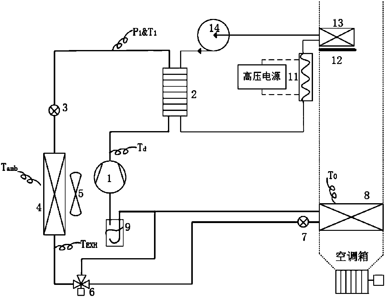
[0056] Such as figure 1 As shown, it is a schematic diagram of the vehicle air-conditioning heat pump integrated system of the present invention, which includes two subsystems: a refrigerant circulation system (heat pump system) and a secondary loop system.

[0057] The refrigerant circulation system includes a compressor 1, a first plate heat exchanger 2, a first electronic expansion valve 3, a heat exchanger 4, a fan 5, a three-way solenoid valve 6, a second electronic expansion valve 7, and an indoor evaporator 8 , and the liquid storage separator 9; wherein:

[0058] The compressor 1, the first plate heat exchanger 2, the first electronic expansion valve 3, the heat exchanger 4, the three-way solenoid valve 6, the second electronic expansion valve 7, the indoor evaporator 8, and the liquid storage separator 9 pass through the pipe The circuits are connected in turn to form a cycle; wherein, the ...

Embodiment 2

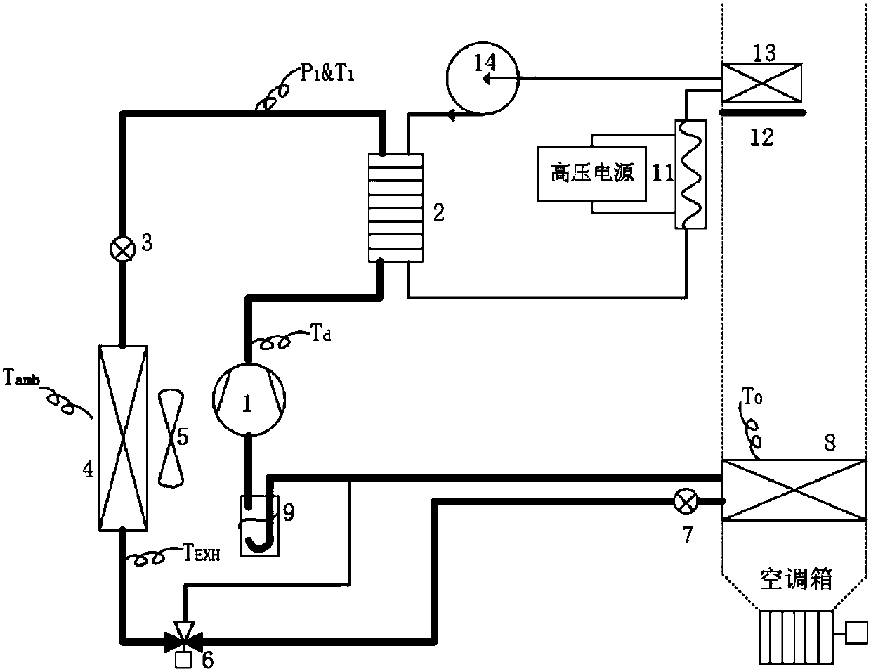
[0065] Embodiment 2, cooling mode

[0066] When the temperature inside the car is high and the temperature inside the car needs to be lowered, the system operates in cooling mode. Such as figure 2 As shown, in the refrigerant circulation system, the high-temperature and high-pressure gaseous refrigerant discharged from the compressor 1 passes through the first plate heat exchanger 2, enters the outdoor heat exchanger 4, releases heat into the atmosphere of the external environment, and becomes a liquid refrigerant, and then After passing through the three-way solenoid valve 6, the liquid refrigerant flows into the second electronic expansion valve 7 for throttling, becomes a low-pressure and low-temperature two-phase refrigerant, and then enters the indoor evaporator 8 to absorb the heat of the air blown by the blower in the air-conditioning box, and becomes a two-phase refrigerant. The phase / gaseous refrigerant enters the liquid storage separator 9, and in the liquid storag...

Embodiment 3

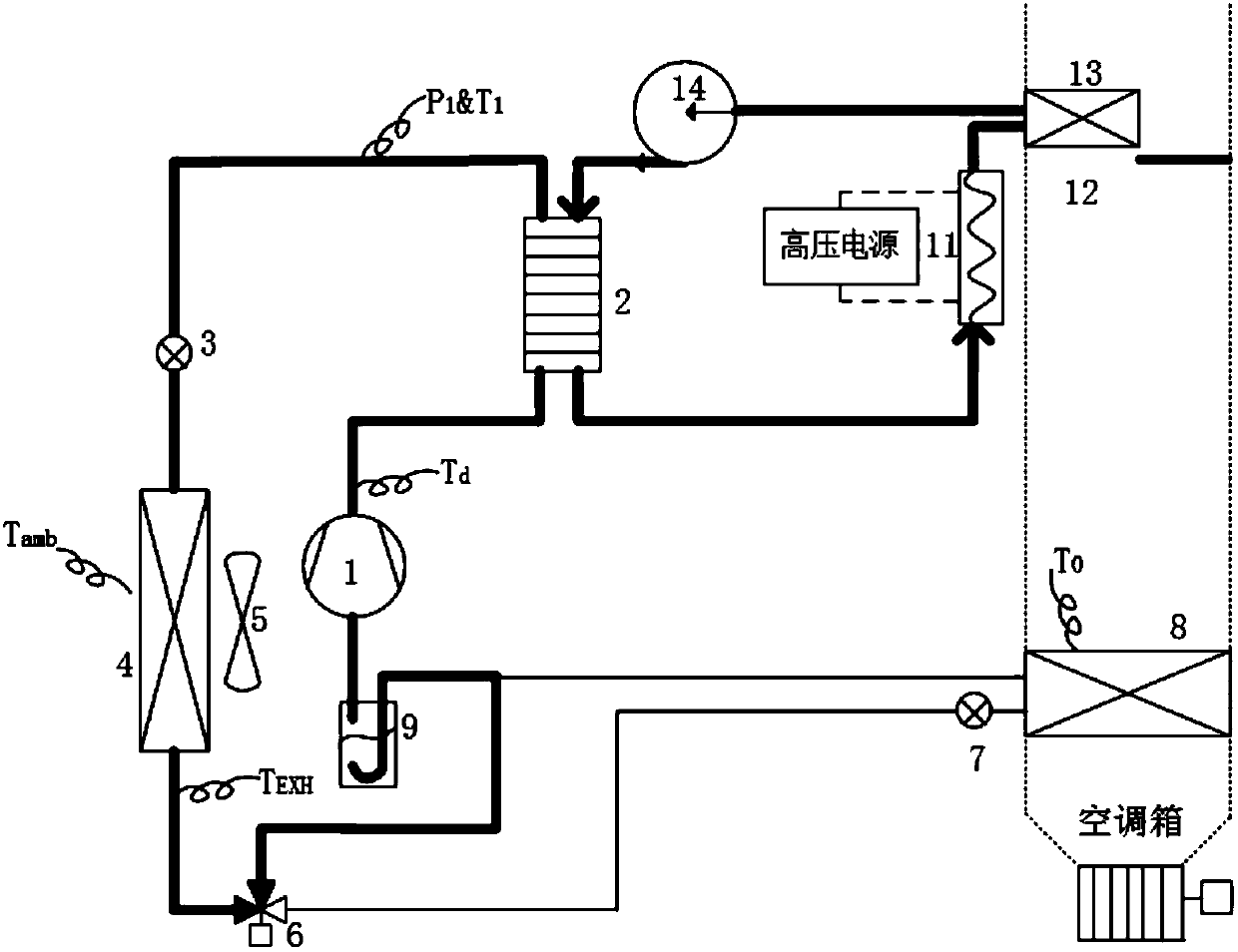
[0068] Embodiment 3, heat pump heating mode

[0069] When the temperature inside the car is low and the car needs to be heated, the system will turn on the heat pump heating mode, because in terms of improving energy utilization, the heating efficiency of the heat pump is greater than 1, while the heating efficiency of PTC water is less than 1, so it will not be used to turn on the PTC heating mode alone. Heat mode, supplying heating to the passenger compartment. Such as image 3 As shown, in the refrigerant circulation system, the high-temperature and high-pressure gaseous refrigerant discharged from the compressor 1 enters the first plate heat exchanger 2, releases heat into the circulating water of the secondary circuit, becomes a liquid refrigerant, and then enters the first electronic expansion valve 3 throttling, it becomes a two-phase refrigerant, and enters the outdoor heat exchanger 4, absorbs the heat of the atmosphere in the external environment, becomes a two-phas...


PUM


Abstract

The invention discloses a vehicle air conditioner and heat pump integrated system. The system comprises two subsystems: a refrigerant circulating system and a secondary loop system, wherein the secondary loop system comprises a first circulating pump, a first plate heat exchanger, a PTC water heater, a temperature air door and an air heating core body; the first circulating pump, the first plate heat exchanger, the PTC water heater and the air heating core body are connected by pipelines to form a cycle; and the air heating core body and the temperature air door are positioned in an air conditioner box. As the secondary loop system is adopted, the heating capacity of the heat pump system can be improved to the greatest extent; and meanwhile, the pressure on a high-pressure side of the refrigerant circulating system is reduced, so that the operating environment of a compressor is improved particularly when the compressor continuously works under a heating mode for a long time.

Description

technical field [0001] The invention belongs to the automotive refrigeration and heating system in the technical field of automobiles, and in particular relates to a vehicle air-conditioning heat pump integrated system. Background technique [0002] With the continuous improvement of people's living standards and the continuous enhancement of environmental protection awareness, new energy electric vehicles are becoming more and more popular. Figure 21 Shown is a schematic diagram of a common new energy vehicle air conditioning system currently on the market. The air conditioning system includes a compressor 110, an outdoor heat exchanger 120, a high pressure liquid storage tank 130, an electronic expansion valve 140, and an evaporator 150 of the air conditioning box, and These components are connected in sequence to form a cycle, wherein a fan 180 is provided on one side of the outdoor heat exchanger 120 . This air conditioning system only has cooling function. When heatin...

Claims


Application Information

Patent Timeline
Patent Type & Authority Applications(China)
IPC IPC(8): F25B1/00F25B41/04F25B41/06F25B47/02F25B49/02B60H1/00B60H1/22B60H1/32F25B41/20F25B41/34
CPCF25B1/00F25B47/022F25B49/02B60H1/00392B60H1/00278B60H1/3207B60H1/2215H01M10/613H01M10/625H01M10/663H01M10/6568H01M10/6554F25B2600/25F25B2600/2513F25B2313/021F25B2313/009F25B2400/01H01M2220/20F25B41/31F25B41/20Y02B30/70Y02E60/10
Inventor 王超杨云顾毅亮吴俊
Owner 上海银轮热交换系统有限公司
Why Eureka
Try Eureka