
Hydrogen separation membrane embedded improved copious cooling liquefying system aiming at STAR propane dehydrogenation process

A technology of propane dehydrogenation and separation membrane, applied in the field of petrochemical industry, can solve the problems of waste, high energy consumption of compression, etc., achieve the effect of reducing energy consumption of compression, reducing energy consumption of compression, and significant economic advantages

Active Publication Date: 2019-08-09
DALIAN UNIV OF TECH
View PDF6 Cites 2 Cited by
  • Summary
  • Abstract
  • Description
  • Claims
  • Application Information

AI Technical Summary

Problems solved by technology

Constrained by the existence of a large number of non-condensable components, the traditional STAR process adopts a cryogenic liquefaction system, which needs to be carried out under high pressure and low temperature conditions of 3.20MPaG and -78°C. The main shortcomings are as follows: 1) All gaseous reaction products need to be produced by 0.50MPaG Pressurize to 3.20MPaG from left to right, and the compression energy consumption is very large; 2) Non-condensable components such as methane and nitrogen coexist with hydrogen in the cryogenic process, and the concentration of by-product crude hydrogen is lower than 90mol%, which cannot be directly used for heating Typical hydrogen consumption processes in refining and chemical enterprises such as hydrocracking and hydrofining, and using it as fuel will cause great waste

Method used


Image

  • Hydrogen separation membrane embedded improved copious cooling liquefying system aiming at STAR propane dehydrogenation process
  • Hydrogen separation membrane embedded improved copious cooling liquefying system aiming at STAR propane dehydrogenation process
  • Hydrogen separation membrane embedded improved copious cooling liquefying system aiming at STAR propane dehydrogenation process

Examples


Embodiment 1

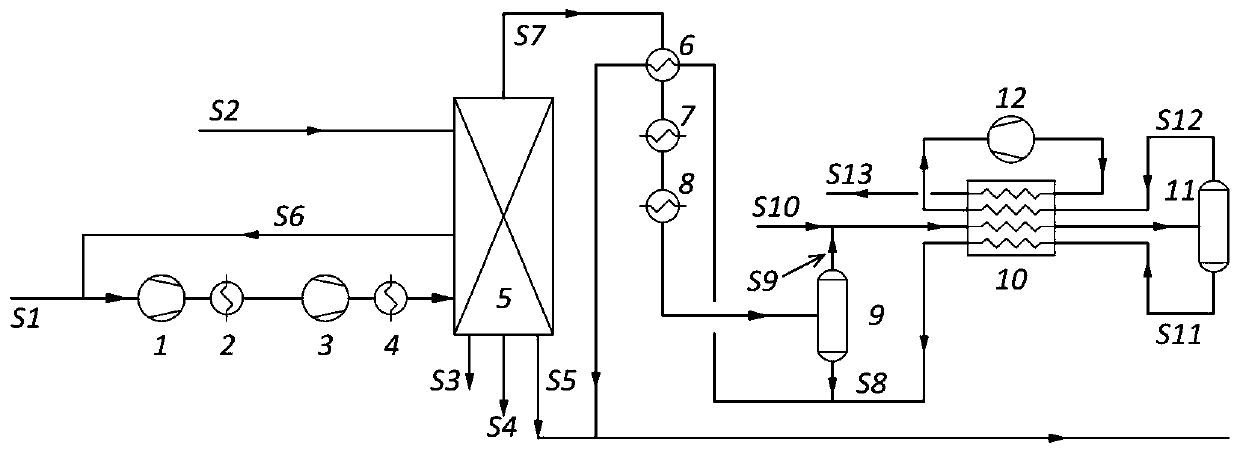
[0021] Example 1 For the propane dehydrogenation reaction product of a typical 350,000-ton STAR process of an enterprise, the traditional cryogenic liquefaction system is used for processing, and the corresponding technical scheme is described as follows:

[0022] Table 2 is a list of the composition and operating parameters of key materials in Example 1.

[0023]

[0024] The propane dehydrogenation reaction product S1 cooled to normal temperature enters the first cooler 2 after being pressurized to 1.40MPaG by the first compressor 1, then enters the second cooler 4 after being further pressurized to 3.20MPaG by the second compressor 3, Lower the temperature of the material to normal temperature, and then enter the decarburization / dehydration system 5. At the same time, the decarbonization absorbent S2 also enters the decarburization / dehydration system 5; in the decarburization / dehydration system 5, five streams of material output are generated, and the decarburization Abs...

Embodiment 2

[0029] Embodiment 2 For the propane dehydrogenation reaction product of a typical 350,000-ton STAR process of a certain enterprise, the improved cryogenic liquefaction system embedded in the hydrogen separation membrane provided by the present invention is used for processing. The specific technical scheme is as follows:

[0030] Table 3 is a list of composition and operating parameters of key materials in Example 2.

[0031]

[0032] Such as figure 2 As shown, the propane dehydrogenation reaction product S1 cooled to normal temperature is pressurized to 1.90MPaG by the first compressor 1 and then enters the first cooler 2, the temperature is lowered to normal temperature, and then enters the decarburization / dehydration system 13, at the same time , the decarburization absorbent S2 also enters the decarburization / dehydration system 13; in the decarbonization / dehydration system 13, five streams of material output are produced, the decarbonization absorbent rich liquid S3 an...

Embodiment 3

[0040] Example 3 For the propane dehydrogenation reaction product of a typical 350,000-ton STAR process of an enterprise, the hydrogen separation membrane provided by the present invention is used to process the improved cryogenic liquefaction system. The specific technical scheme is as follows:

[0041] Table 5 is a list of composition and operating parameters of key materials in Example 3.

[0042]

[0043]

[0044] Such as figure 2 As shown, the propane dehydrogenation reaction product S1 cooled to normal temperature is pressurized to 2.30MPaG by the first compressor 1 and then enters the first cooler 2, the temperature is lowered to normal temperature, and then enters the decarburization / dehydration system 13, and at the same time , the decarburization absorbent S2 also enters the decarburization / dehydration system 13; in the decarbonization / dehydration system 13, five streams of material output are produced, the decarbonization absorbent rich liquid S3 and condense...


PUM


Abstract

The invention provides a hydrogen separation membrane embedded improved copious cooling liquefying system aiming at an STAR propane dehydrogenation process, and belongs to the technical field of petrochemical engineering. According to the system, starting from the composition characteristics of dehydrogenation reaction products, a hydrogen membrane separation unit is introduced behind a shallow cooling unit, most hydrogen is separated through selective permeation of a membrane, then pressurizing and copious cooling liquefying are further carried out, and propane and propylene are further separated from remaining non-condensable components. By means of the hydrogen membrane separation unit embedded improved copious cooling liquefying system, compression loads can be remarkably reduced whilehigh-concentration hydrogen is obtained, the total compression energy consumption can be reduced by 8-24%, the heat exchange load of a copious cooling unit can be reduced by 80-86%, the purity of thebyproduct hydrogen can be increased from 82 mol% to 99 mol%, and the requirements of hydrogen consumption devices such as hydrocracking devices in the refinery enterprise are met. Under the optimum working condition, by means of the 350,000-ton STAR process, 1020 kW of the compression energy consumption can be reduced, and 16,198 Nm<3> / h of qualified hydrogen is output.

Description

technical field [0001] The invention relates to an improved cryogenic liquefaction system embedded with a hydrogen separation membrane for the STAR propane dehydrogenation process, which belongs to the field of petrochemical industry. In this process, a hydrogen membrane separation unit is embedded between the shallow cooling unit and the cryogenic unit, and most of the hydrogen in the reaction product is removed through the selective permeation of the membrane, and the non-phase-change concentration of propane and propylene is carried out, greatly reducing the gas flow rate, and then Further pressurization and cryogenic liquefaction can reduce the compression energy consumption of the cryogenic liquefaction process while obtaining high-concentration hydrogen. Background technique [0002] Propylene is the basic raw material for three major synthetic materials including plastics, synthetic rubber and synthetic fibers. In addition, propylene is also widely used in the produc...

Claims


Application Information

Patent Timeline
Patent Type & Authority Applications(China)
IPC IPC(8): F25J3/08B01D61/00
CPCB01D61/00F25J3/08
Inventor 阮雪华贺高红肖红岩姜晓滨肖武焉晓明代岩张宁
Owner DALIAN UNIV OF TECH
Learn More