Optical fiber vibration sensor based on delayed phase-modulated chirped pulse pairs

A technology of chirped pulse and fiber vibration, applied in instruments, optics, nonlinear optics, etc., can solve problems such as interference fading, and achieve the effect of reducing influence and solving interference fading

Active Publication Date: 2019-08-09
SHANGHAI INST OF OPTICS & FINE MECHANICS CHINESE ACAD OF SCI
View PDF7 Cites 9 Cited by
  • Summary
  • Abstract
  • Description
  • Claims
  • Application Information

AI Technical Summary

Problems solved by technology

[0006] The purpose of the present invention is to overcome the mutual restriction and contradictory relationship between the sensitivity and spatial resolution of the existing optical fiber sensing system and the sensing distance, solve the interference fading problem existing in the system at the same time, and improve the Φ-OTDR A number of key indicators to build a high-performance Φ-OTDR sensing system

Method used


Image

  • Optical fiber vibration sensor based on delayed phase-modulated chirped pulse pairs
  • Optical fiber vibration sensor based on delayed phase-modulated chirped pulse pairs
  • Optical fiber vibration sensor based on delayed phase-modulated chirped pulse pairs

Examples


Embodiment Construction

[0033] The present invention will be further described below in conjunction with the embodiments and accompanying drawings, but the protection scope of the present invention should not be limited thereby.

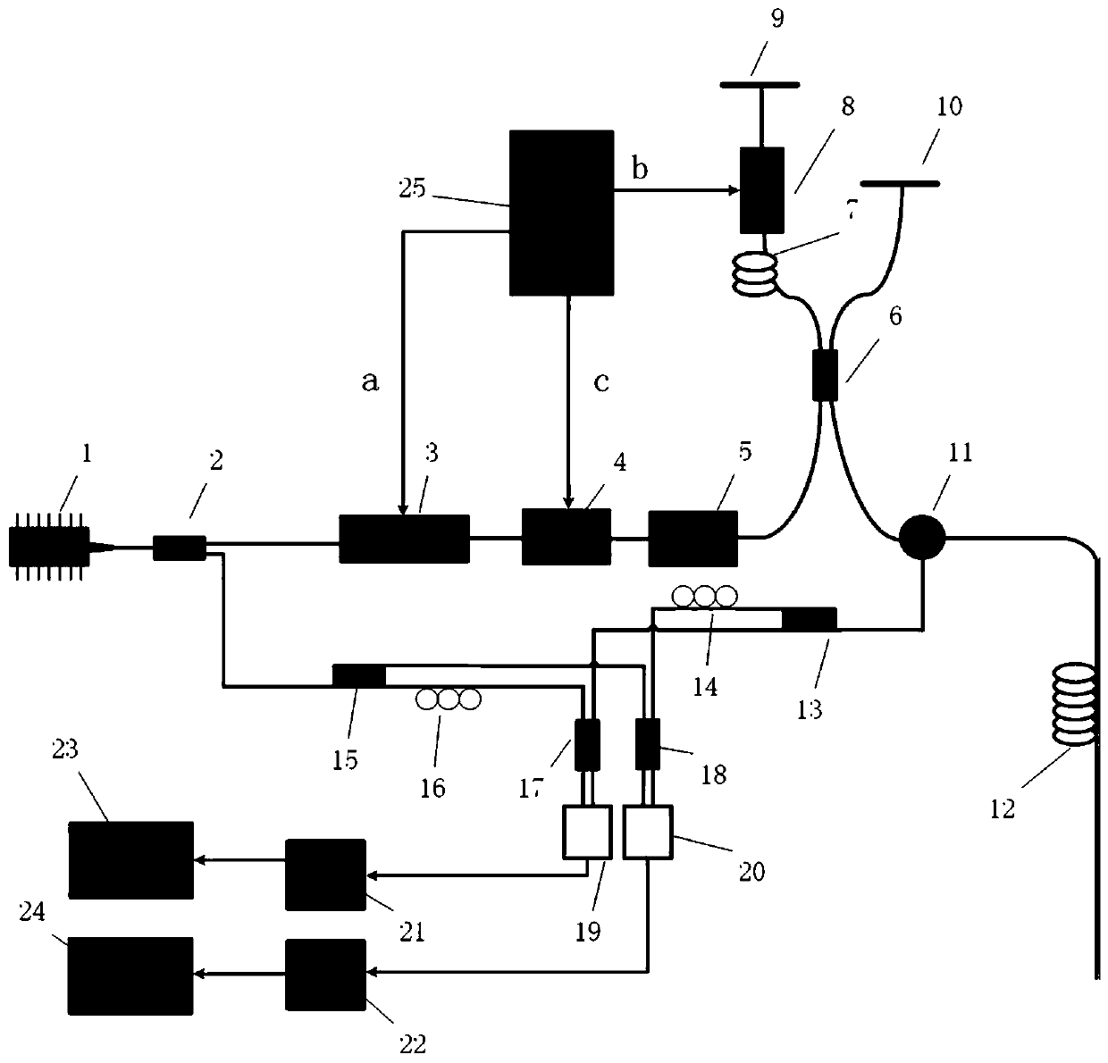
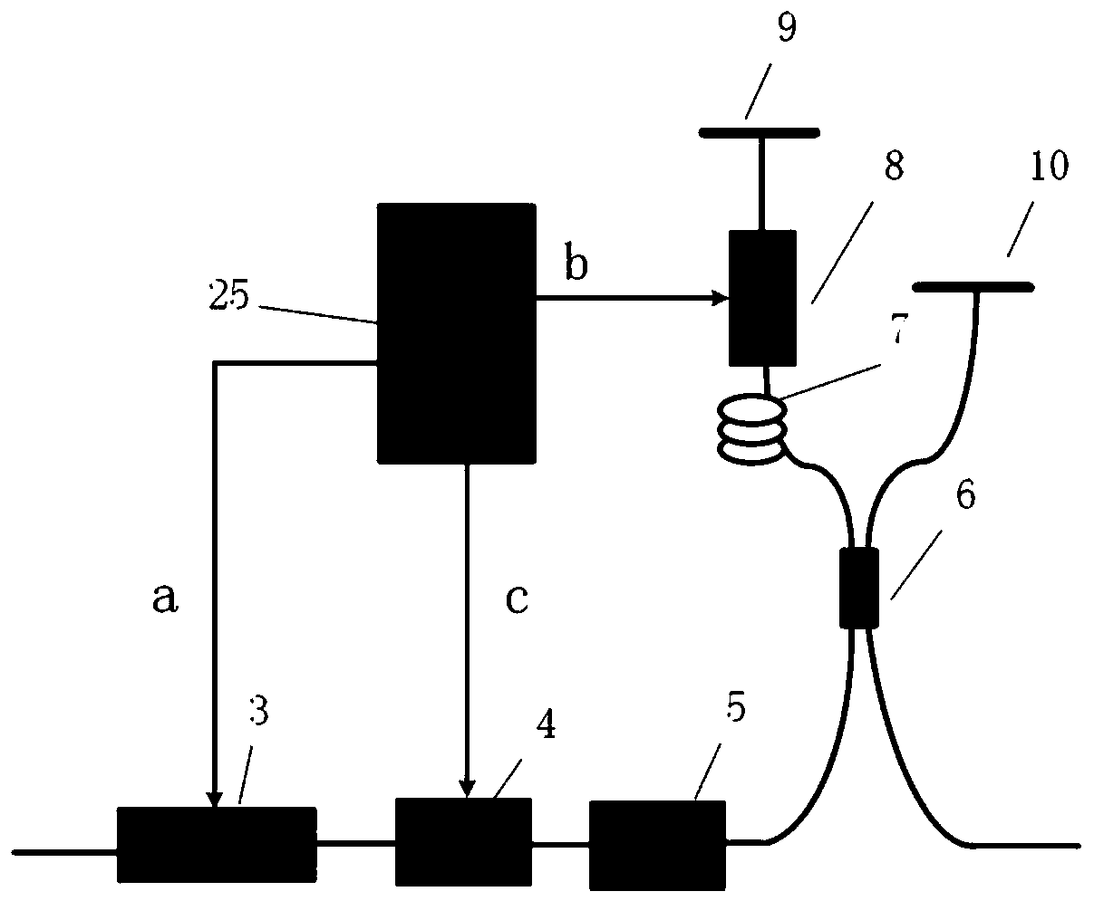
[0034] Please refer to figure 1 , figure 1 It is a block diagram of the overall structure of the optical fiber vibration sensor based on the delay-phase-modulated chirped pulse pair of the present invention. Depend on figure 1 It can be seen that the high-performance optical fiber vibration sensing device based on delayed phase-modulated chirped pulse pairs of the present invention comprises a narrow linewidth laser 1, a first fiber coupler 2, an electro-optic modulator 3, an acousto-optic modulator 4, and an optical amplifier 5 , the second fiber coupler 6, the delay fiber 7, the fiber retractor 8, the first Faraday rotating mirror 9, the second Faraday rotating mirror 10, the circulator 11, the third fiber coupler 13, the first polarization controller 14, the first Fou...


PUM

PropertyMeasurementUnit
wavelengthaaaaaaaaaa

Abstract

The invention relates to an optical fiber vibration sensor based on delay phase-modulated chirped pulse pairs. The sensor comprises a narrow linewidth laser, a first optical fiber coupler, an electro-optical modulator, an acousto-optic modulator, an optical amplifier, a second optical fiber coupler, a delay optical fiber, an optical fiber expansion device, a first Faraday rotator mirror, a secondFaraday rotator mirror, an annular device, a to-be-measured optical fiber, a third optical fiber coupler, a first polarization controller, a fourth optical fiber coupler, a second polarization controller, a fifth optical fiber coupler, a sixth optical fiber coupler, a first double-balance detector, a second double-balance detector, a first analog-to-digital converter, a second analog-to-digital converter, a first digital signal processing unit, a second digital signal processing unit and an arbitrary waveform generator. With the optical fiber vibration sensor adopted, the contradiction betweenspatial resolution and sensing distances in a traditional sensing system based on a time-domain reflectometer can be eradicated; the problem of interference attenuation in an interference sensing system can be solved; and indexes such as a long sensing distance, high spatial resolution and a high signal-to-noise ratio can be achieved simultaneously.

Description

technical field [0001] The invention relates to the technical field of distributed optical fiber sensing, in particular to a high-performance optical fiber vibration sensor based on delayed phase modulation chirped pulse pairs. Background technique [0002] Optical fiber sensor has strong anti-electromagnetic interference ability, non-invasiveness, easy to realize long-distance monitoring of the measured signal, corrosion resistance, explosion-proof, flexible optical path, easy to connect with optical fiber system and other advantages. In recent years, it has been widely used in natural gas and oil pipeline safety monitoring, bridge crack monitoring, gas concentration detection, border security and other fields. [0003] Phase-sensitive optical time domain reflectometer (Φ-OTDR) is a new type of distributed optical acoustic sensing technology (DAS), which can realize distributed dynamic detection by using the backward Rayleigh scattering in optical fiber. The main performan...

Claims


Application Information

Patent Timeline
Patent Type & Authority Applications(China)
IPC IPC(8): G01H9/00G02F1/095
CPCG01H9/004G02F1/0955
Inventor 卢斌王照勇叶青蔡海文叶蕾
Owner SHANGHAI INST OF OPTICS & FINE MECHANICS CHINESE ACAD OF SCI
Why Eureka
Try Eureka