Method for measuring elevation of independent structure

A structure and elevation technology, which is applied in measuring devices, height/level measurement, surveying and navigation, etc., can solve problems such as high operating costs, personal injuries, and low measurement accuracy, so as to achieve accurate and reliable measurement data, avoid climbing, The effect of high measurement accuracy

Inactive Publication Date: 2019-08-13
CHINA FIRST METALLURGICAL GROUP
View PDF4 Cites 2 Cited by
  • Summary
  • Abstract
  • Description
  • Claims
  • Application Information

AI Technical Summary

Problems solved by technology

This method requires surveyors to arrive at the point to be measured to place a GNSS receiver. It requires an open field, good satellite and network signals, and far away from radio transmission sources, high-voltage power lines, microwave towers, etc. This method is limited by satellites, network signals and the surrounding environment. higher operating costs
[0008] 4. Total station suspension height measurement: use the total station to measure the vertical height difference between a certain point in the air and the ground, and then obtain the elevation of the point to be measured according to the height difference between the ground point and the known point, and the surveyor needs to reach the target point to be measured A reflective prism is placed on the vertical bottom of the ground, this method is only suitable for measuring the elevation of a certain point in the air (such as a suspended high-voltage line)
[0011] The above methods 1, 2, 3 and 4 all require surveyors to arrive at the point to be measured and install measuring equipment (a vertical ruler, a prism, a GNSS measuring instrument, etc.), and the structures on the top of the mountain, on the edge of the cliff, and in the middle of the water are due to their special locations. It is very difficult for surveyors to reach the point to be measured. For structures with dangerous sources such as high voltage or radiation, surveyors close to the structure will have a greater risk of personal injury, such a

Method used


Image

  • Method for measuring elevation of independent structure
  • Method for measuring elevation of independent structure

Examples


Embodiment Construction

[0037] In order to make the purpose, technical solutions and advantages of the embodiments of the present invention clearer, the technical solutions in the embodiments of the present invention will be clearly and completely described below in conjunction with the drawings in the embodiments of the present invention. Obviously, the described embodiments It is a part of embodiments of the present invention, but not all embodiments. It should be understood that the specific embodiments described here are only used to explain the present invention, not to limit the present invention. Based on the embodiments of the present invention, all other embodiments obtained by persons of ordinary skill in the art without making creative efforts belong to the protection scope of the present invention.

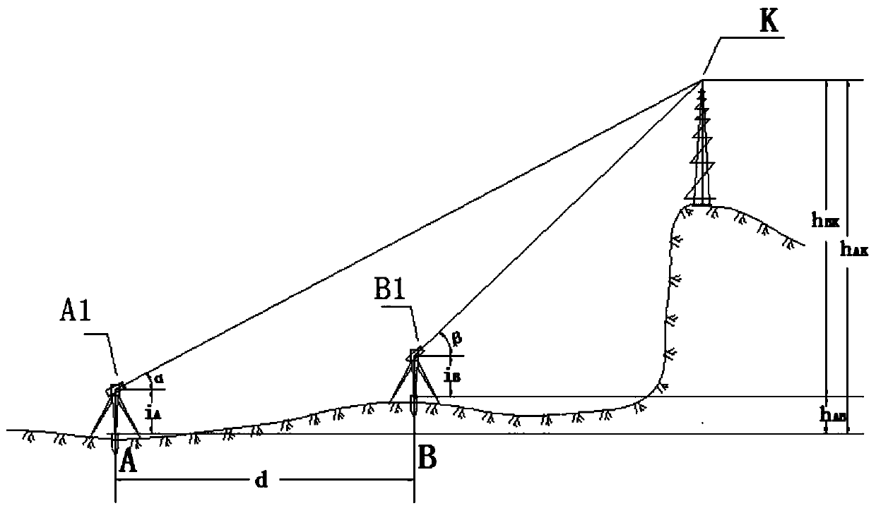
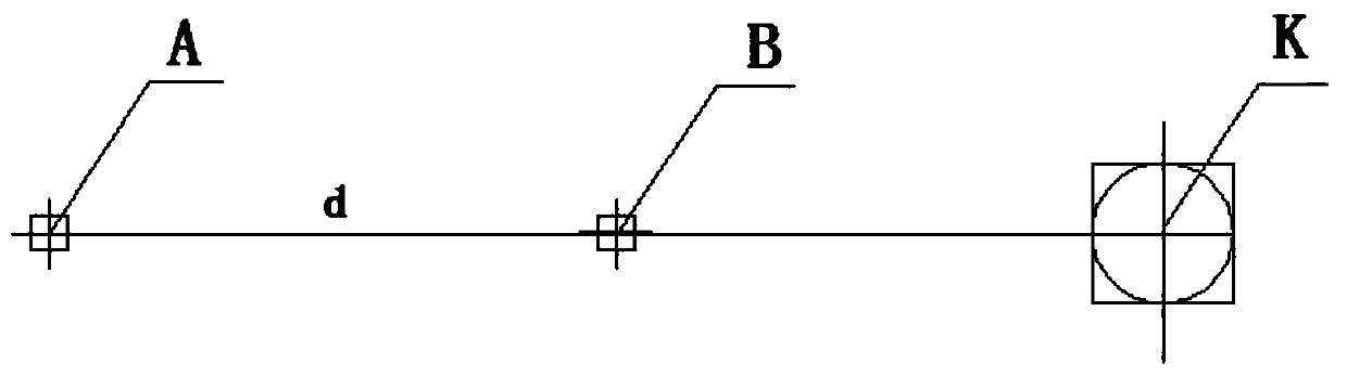
[0038] Such as Figure 1-2As shown, a method for measuring the elevation of independent structures includes the following steps:

[0039] (1) On the ground away from the structure to be mea...


PUM


Abstract

The invention discloses a method for measuring the elevation of an independent structure, which comprises the following steps: selecting two survey stations, which are in communication with a to-be-measured point and are positioned on the same vertical plane, on the ground far away from the structure to be measured according to the angle measurement and distance measurement integrated function ofa total station and the advantages and characteristics of accurate data and convenience in operation of the total station and by combining a certain mathematical theory; erecting the total station atthe two survey stations respectively; observing two vertical angles and a section of horizontal distance; calculating the height difference between the top end of the structure to be measured and thesurvey stations through mathematical calculation; and obtaining the accurate elevation of the independent structure conveniently and quickly through the relationship between known points on the groundand the survey stations. The method for measuring the elevation of the independent structure can quickly finish the measurement work by only two persons.

Description

technical field [0001] The invention belongs to the technical field of buildings, in particular to a method for measuring the elevation of independent structures. Background technique [0002] In the design and construction of some projects (such as airports), in order to meet the requirements of the function, layout and safety of the construction project, it is necessary to obtain the elevation of the proposed project site and the surrounding original structures. The methods used to measure the elevation of structures are generally Surveying, triangulation elevation measurement, GNSS elevation measurement, total station suspension height measurement, aerial photography and remote sensing measurement, etc. Among them, the aerial photography and remote sensing method have limited accuracy of the measured height due to their high cost, and the other methods are difficult to measure. Surveyors need to arrive at the point to be measured to install measuring equipment such as ver...

Claims


Application Information

Patent Timeline
IPC IPC(8): G01C5/00
CPCG01C5/00
Inventor 何红玲刘思农魏民廖红玉刘明周王军
Owner CHINA FIRST METALLURGICAL GROUP
Why Eureka
Try Eureka