High-flux plasma reaction apparatus and hydrogen sulfide decomposing method

A reaction device and plasma technology, which is applied in the field of plasma chemistry, can solve the problems of low conversion rate of hydrogen sulfide, high energy consumption, and inability to realize large flow, and achieve high conversion rate of hydrogen sulfide, low energy consumption, and long cycle running effect

Pending Publication Date: 2019-08-16
CHINA PETROLEUM & CHEM CORP +1
View PDF5 Cites 0 Cited by
  • Summary
  • Abstract
  • Description
  • Claims
  • Application Information

AI Technical Summary

Problems solved by technology

[0015] The purpose of the present invention is to provide a new high-pass Quantitative plasma reaction device and method for decomposing hydrogen sulfide using the high-flux plasma reaction device

Method used


Image

  • High-flux plasma reaction apparatus and hydrogen sulfide decomposing method

Examples


specific Embodiment approach

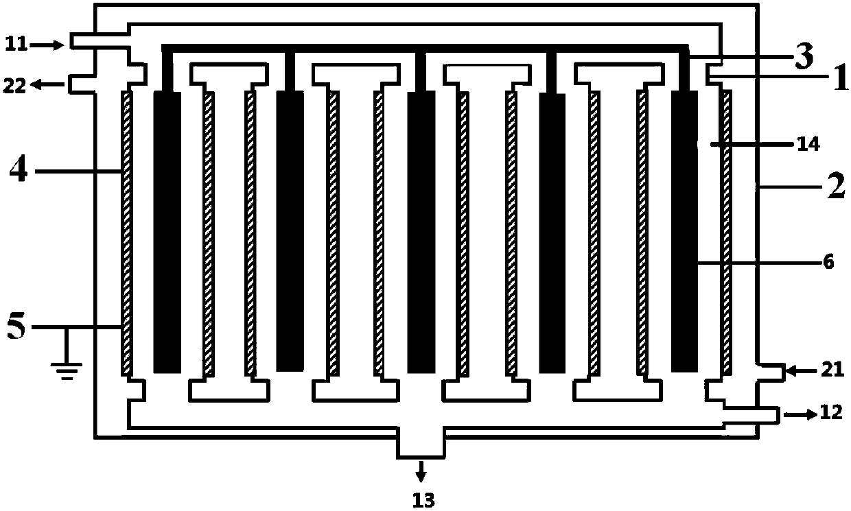
[0094]Nitrogen gas is passed from the reactor inlet to the inner cylinder of the high-flux plasma reaction device to remove the air in the discharge area, and the gas is drawn out from the product outlet. At the same time, the heat transfer medium is introduced into the outer cylinder from the heat transfer medium inlet, and the introduced heat transfer medium is led out from the heat transfer medium outlet. The temperature of the heat transfer medium is maintained at the temperature required by the system reaction. Then feed raw material gas containing hydrogen sulfide from the reactor inlet to the inner cylinder of the high-throughput plasma reaction device. The raw material gas fills each reaction tube. A plasma discharge field is formed between the high voltage electrode and the ground electrode. The hydrogen sulfide gas is ionized in the discharge area and decomposed into hydrogen and elemental sulfur. The elemental sulfur produced by the discharge slowly flows down the ...

Embodiment 1

[0106] use figure 1 The shown high-flux plasma reaction device performs hydrogen sulfide decomposition reaction. The specific structure and structural parameters of the high-flux plasma reaction device are as follows:

[0107] The reaction unit includes:

[0108] An inner cylinder, the inner cylinder is respectively provided with a reactor inlet, a gas product outlet and a liquid product outlet, and the inner cylinder contains 4 reaction tubes arranged side by side, and the top and bottom of each of the reaction tubes communicate with each other respectively , so that the raw materials entering by the reactor inlet can enter into each of the reaction tubes respectively, and the gaseous products produced in each of the reaction tubes can be drawn out from the gas product outlet, and each of the reaction tubes The liquid product produced in can be drawn out by the liquid product outlet, and the size of the four reaction tubes is exactly the same;

[0109] An outer cylinder, th...

Embodiment 2

[0137] In this embodiment, a high-throughput low-temperature plasma reactor similar to that of Embodiment 1 is used to carry out the decomposition reaction of hydrogen sulfide. The difference is that in this embodiment:

[0138] All side walls of the reaction tube are formed by ground electrodes, and the material forming the ground electrodes is stainless steel metal foil;

[0139] In each reaction tube, the distance L between the outer wall of the barrier medium and the inner wall of the ground electrode 1 and the length of the discharge area L 2 The ratio is 1:3000;

[0140] The height H of the setting position of the gas product outlet relative to the bottom of the inner cylinder 1 and the length L of the discharge region in each reaction tube 2The proportional relationship between is: H 1 :L 2 =1:250;

[0141] L 1 with the thickness of the barrier dielectric D 1 The proportional relationship between them is: L 1 :D 1 =15:1;

[0142] In this embodiment, H is pass...


PUM


Abstract

The invention relates to the field of plasma chemistry, and discloses a high-flux plasma reaction apparatus and a hydrogen sulfide decomposing method. The high-flux plasma reaction apparatus comprises: an inner cylinder (1) containing reaction pipes (14); an outer cylinder (2) nested on the outer portion of the inner cylinder (1); center high-voltage electrodes (3); grounding electrodes (4) respectively arranged around the outer side walls of each reaction pipe (14) or forming the side wall; and a barrier medium arranged on at least part of the outer surface of the center high-voltage electrode (3), wherein a ratio (L1:L2) of the distance L1 between the outer side wall of the barrier medium and the inner side wall of the grounding electrode and the length L2 of a discharge area is (0.5-6000). According to the present invention, the apparatus can achieve the continuous and stable performing of a hydrogen sulfide decomposing process at a significantly high hydrogen sulfide conversion rate, and can achieve long-period operation.

Description

technical field [0001] The invention relates to the field of plasma chemistry, in particular to a high-throughput plasma reaction device and a method for decomposing hydrogen sulfide. Background technique [0002] Hydrogen sulfide (H 2 S) is a highly toxic and foul-smelling acid gas, which not only causes corrosion of metals and other materials, but also endangers human health and pollutes the environment. At present, large and medium-sized refineries in my country adopt the traditional Claus method (Claus) to treat 2 S tail gas, and recover sulfur. The method recovers only the sulfur in hydrogen sulfide, but converts the valuable hydrogen into water. From the perspective of comprehensive utilization of resources, hydrogen resources have not been effectively utilized in the traditional hydrogen sulfide recovery process. Therefore, the decomposition of hydrogen sulfide into sulfur and hydrogen has gradually become a technical field that researchers at home and abroad pay ...

Claims


Application Information

Patent Timeline
Patent Type & Authority Applications(China)
IPC IPC(8): B01D53/32B01D53/52C01B3/04C01B17/04
CPCB01D53/32B01D53/323B01D53/52B01D2256/16B01D2259/818C01B3/04C01B17/04Y02E60/36
Inventor 张婧姜春明张铁任君朋孙峰金满平徐伟石宁
Owner CHINA PETROLEUM & CHEM CORP
Why Eureka
Try Eureka