

Laser processing device and method for film material removal
A laser processing and thin-film material technology, applied in the laser field, can solve the problems of complex flat-top spot shaping technology and difficult application of thin-film materials, and achieve the effects of smooth edges, improved product yield and quality, and strong practicability
Active Publication Date: 2019-08-16
WUHAN HGLASER ENG CO LTD
View PDF7 Cites 13 Cited by
- Summary
- Abstract
- Description
- Claims
- Application Information
AI Technical Summary
Problems solved by technology
[0005] The purpose of the present invention is to address the problems existing in the prior art, provide a laser processing device and method for thin film material removal, and solve the problems of complex flat top spot shaping technology and difficult application of thin film materials
Method used
View moreImage
Smart ImageViewing Examples

Examples
Embodiment 1
[0052] In one embodiment of the device and method disclosed herein, a picosecond laser with a power of 50W and a wavelength of 1064nm is used to process a 0.3mm thick cop plastic surface paint layer at a processing speed of 300mm / s. After processing, the cop plastic The surface paint layer is removed cleanly, there is no taper, no heat effect, and the roughness of the processed bottom is 0.2um.
Login to View More PUM
 Abstract
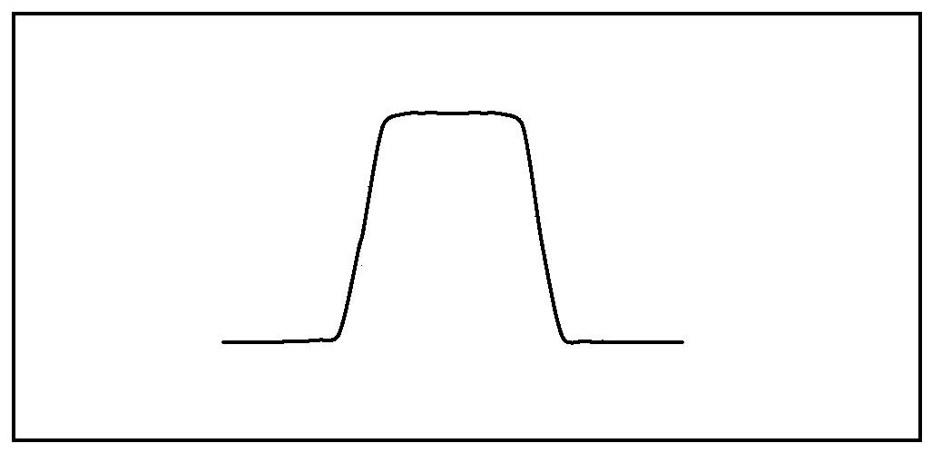
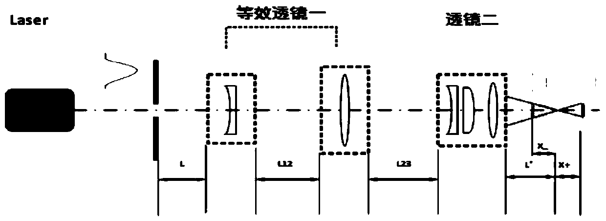
The invention discloses a laser processing device for film material removal. A laser, a small aperture diaphragm and a lens system are arranged in sequence along a laser light propagation path. The lens system comprises a first equivalent lens and a second lens. Gaussian beam emitted by the laser passes through the small aperture diaphragm and the lens system and then forms an image with sharp edges, meanwhile, after the Gaussian beam passes through the small aperture diaphragm, diffraction orders with unobvious edges occur due to the diffraction phenomenon, and light spots of Gaussian beam are imaged into sharp-edged and flat-topped light after different diffraction orders are gathered and superimposed through the lens system. The invention further discloses a laser processing method forfilm material removal. Through the device and method disclosed by the invention, the problems that a flat-topped light spot shaping technology is complicated, and application to film materials is difficult are solved.
Description
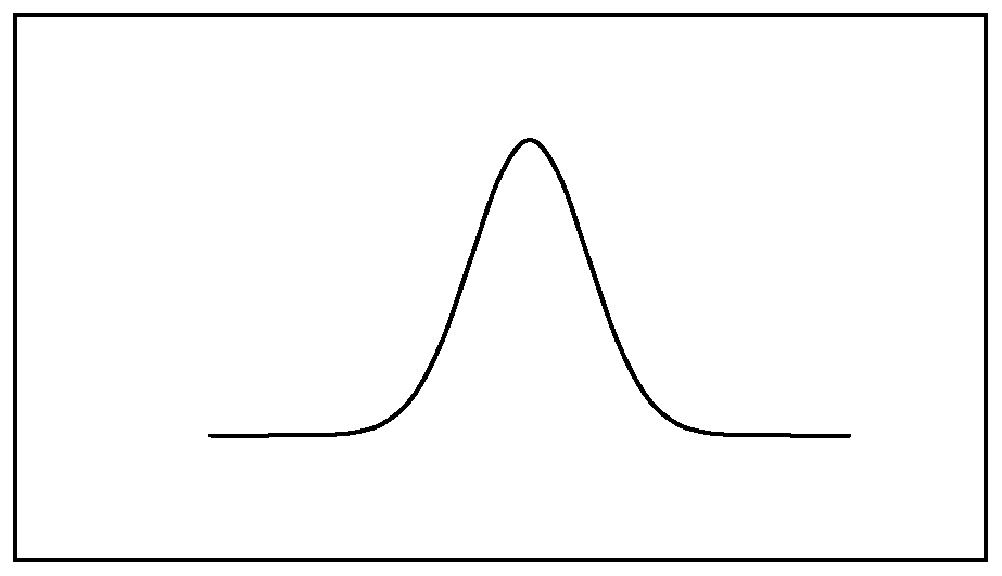
technical field [0001] The invention relates to the field of laser technology, in particular to a laser processing device and method for removing thin film materials. Background technique [0002] With the development of laser technology and the deepening of laser research, the application fields and application methods of laser processing have also expanded, and the requirements are also extremely high. The general laser output is the fundamental mode, and the cross-sectional light intensity in the beam propagation direction is Gaussian distribution, such as figure 1 As shown, it shows a distribution that is strong in the middle and gradually weakens around the periphery. Therefore, when the laser with Gaussian irradiance distribution is used to selectively remove thin film materials on the surface of heat-sensitive substrates, due to the difference in light intensity between the middle region and the edge region, or the middle region reaches a suitable energy density in a...
Claims
Login to View More Application Information
Patent Timeline
 Patent Type & AuthorityApplications(China)
IPC IPC(8): B23K26/06B23K26/064B23K26/36B23K26/402
CPCB23K26/0648B23K26/36B23K26/402B23K26/064
Inventor王雪辉王建刚温彬王玉莹白娟娟
OwnerWUHAN HGLASER ENG CO LTD