
Conformal cutting layer and path planning method for curved surface 3D printing

A path planning and 3D printing technology, applied in the field of surface 3D printing, which can solve the problem of failure to consider the force distribution and path shape when the part is stressed, can not fully adapt to surface layering and path planning, ignore the impact of mechanical properties of parts, etc. problems, to save material and printing time, improve step effects, reduce gaps and voids

Active Publication Date: 2019-08-16
XI AN JIAOTONG UNIV
View PDF6 Cites 26 Cited by
  • Summary
  • Abstract
  • Description
  • Claims
  • Application Information

AI Technical Summary

Problems solved by technology

[0005] To sum up, the existing layer-slicing and path planning technologies for curved surface 3D printing have a narrow scope of application and can only solve specific simple cases, and are not general; at the same time, most methods are based on plane-oriented layer-slicing and path planning technologies. It is improved from above, and still uses Euclidean measurement, which cannot fully meet the requirements of surface layering and path planning, and some methods of path planning using geodesic distance also fail to consider the force line distribution and path shape when the part is stressed. relationship, ignoring the influence of the optimized path direction on the mechanical properties of the part

Method used


Image

  • Conformal cutting layer and path planning method for curved surface 3D printing
  • Conformal cutting layer and path planning method for curved surface 3D printing
  • Conformal cutting layer and path planning method for curved surface 3D printing

Examples


Embodiment Construction

[0039] The present invention will be further described in detail below in conjunction with the accompanying drawings and embodiments.

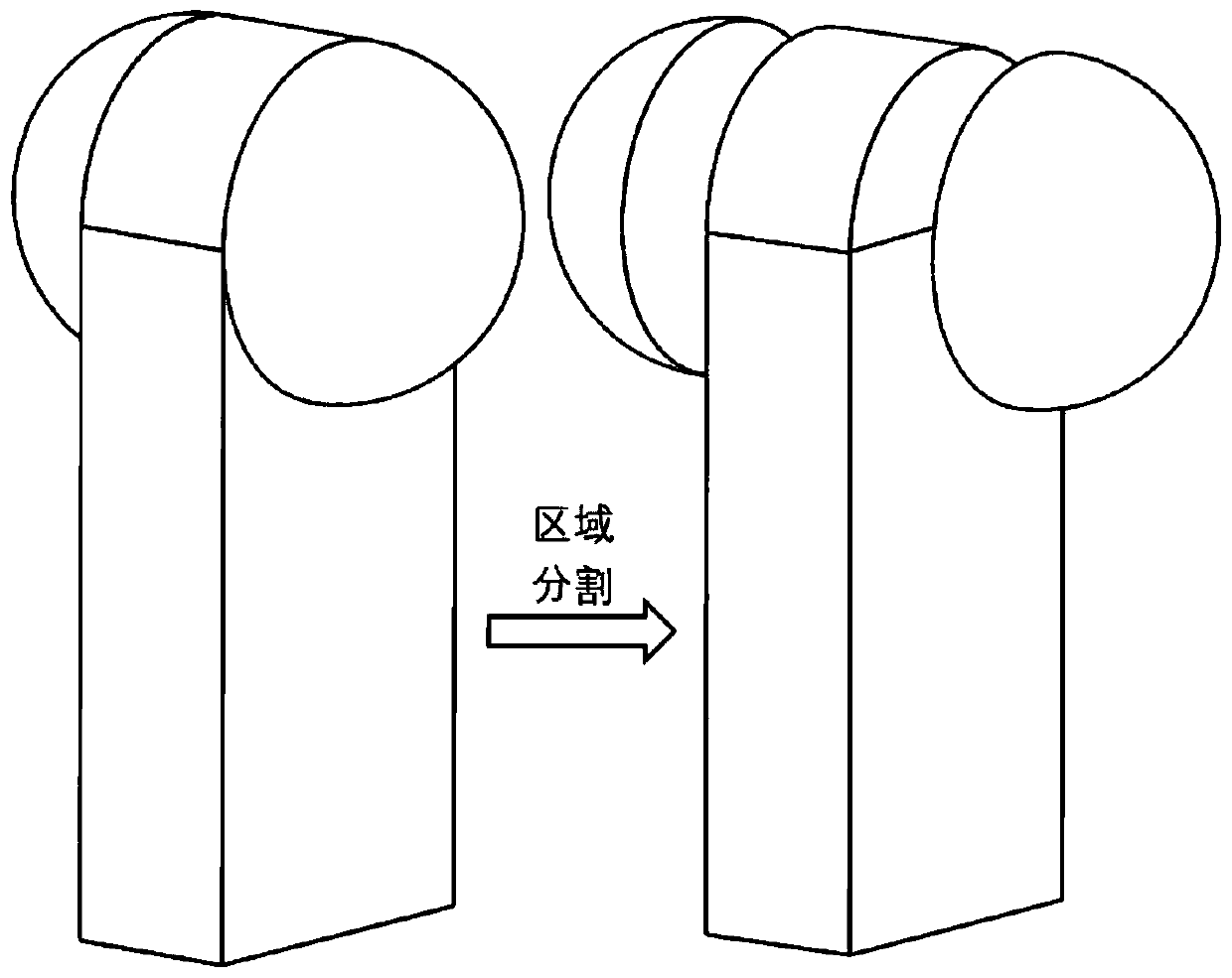
[0040] This embodiment performs model layering and spatial path planning for the FDM process. The model to be printed is as follows: figure 2 As shown, the file format is OBJ, and the multi-axis printer used is composed of two parts: the upper nozzle is fixed at the end of the ABB six-degree-of-freedom robotic arm, and the lower part, which is used to carry parts, is fixed on the two-axis turntable.

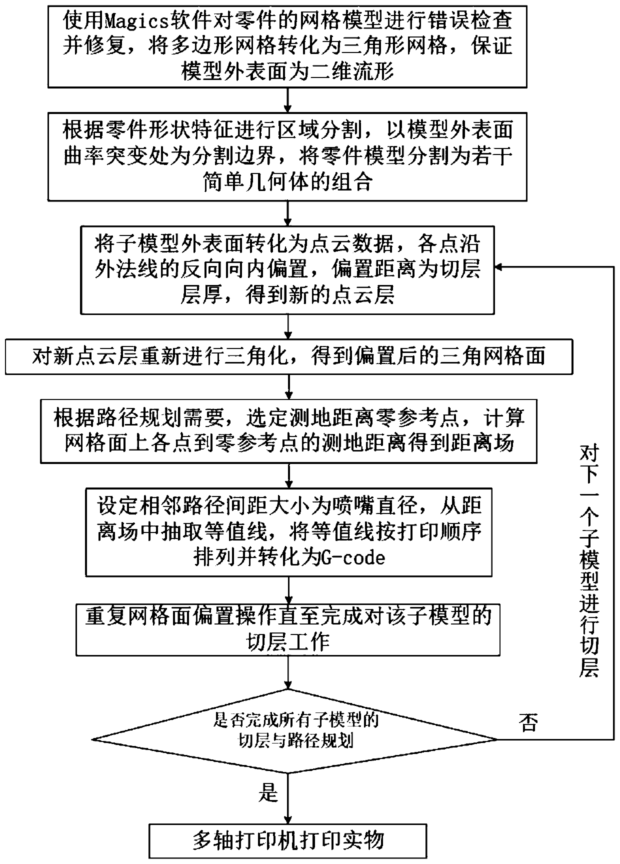
[0041] refer to figure 1 , a method for conformal layer slicing and path planning for curved surface 3D printing, comprising the following steps:

[0042] 1) Use Solidworks software to establish such as figure 2 (Left) Part model M as shown, then save the model as a file in OBJ format, check its outer surface S 0 Whether it is a two-dimensional manifold, if the meshes in the model are not all triangular units, first perform mesh triangulatio...


PUM


Abstract

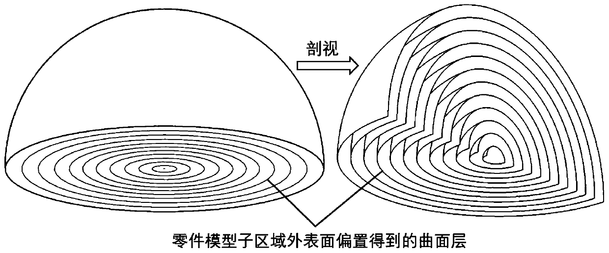
The invention discloses a conformal cutting layer and path planning method for curved surface 3D printing. The conformal cutting layer comprises a conformal curved surface cutting layer method and a three-dimensional space path planning method, the conformal curved surface cutting method comprises the following steps that defect inspection and repairing are carried out on a grid model, it is ensured that the outer surface of the model is a two-dimensional flow shape, if the grid surface is not an all-triangular unit, triangular formation is carried out on the grid surface; then regional segmentation is carried out, the printing sequence of each sub-portion and the approximate direction of the sub-layer are determined; the outer surface is converted into point cloud data, and the point cloud is biased inwards; the offset point cloud data is fit to form a triangular mesh surface; and the model is correspondingly divided into a plurality of curved surface layers to obtain a curved surfaceset; and the three-dimensional space path planning method comprises the following steps of checking whether the curved surface in the curved surface set is the two-dimensional flow shape or not, homogenizing the triangular unit, calculating the geodesic distance of each vertex of the grid relative to the designated reference point, extracting equivalent points, fitting to be a contour line, and converting into a G-code to obtain a printing path. According to the conformal cutting layer and path planning method, the special requirements of curved surface printing can be met.

Description

technical field [0001] The invention relates to the technical field of curved surface 3D printing, in particular to a method for conformal slicing and path planning for curved surface 3D printing. Background technique [0002] The layer-slicing method of traditional 3D printing technology is usually plane layering, that is, the outline information of each layer is obtained by layering the model stored in the file format of STL, AMF or 3MF, and then the path is completed by combining the path filling method and process parameters. planning. Due to the "step effect" of the parts printed by this method of plane slice, the surface quality is poor, and the layers are easy to crack, resulting in anisotropy of mechanical properties, and it is necessary to add support under the cantilever structure, resulting in increased printing time and consumed The increase in material makes it difficult to remove the support structure after printing. [0003] In view of the limitations of the...

Claims


Application Information

Patent Timeline
IPC IPC(8): B29C64/393B33Y50/02
CPCB29C64/393B33Y50/02
Inventor 崔滨李良刚刘亚雄
Owner XI AN JIAOTONG UNIV
Learn More