A millimeter wave indoor passive coverage method

A millimeter wave and electromagnetic wave technology, applied in wireless communication, electrical components, network planning, etc., can solve the problems of limited application scenarios of reflectors, complex composition structures, poor antenna fusion, etc., to overcome poor antenna fusion, Overcoming the high cost of the antenna and improving the effect of the antenna gain

Active Publication Date: 2020-11-20
XIDIAN UNIV
View PDF6 Cites 0 Cited by
  • Summary
  • Abstract
  • Description
  • Claims
  • Application Information

AI Technical Summary

Problems solved by technology

However, there are still three problems in this invention, one is that the application scenarios of the reflector are limited; the other is that the gain of the reflector is low, and to cover a large range of blind areas, it is necessary to add multiple reflectors, which causes the cost to increase; The third is that the fusion between the reflector and the environment is poor
[0005] To sum up, the current millimeter-wave indoor coverage method faces two problems. One is that the existing millimeter-wave indoor coverage method has limited application scenarios and complex composition structures; the other is that the existing millimeter-wave indoor coverage antenna is compatible with Environmental integration is poor

Method used


Image

  • A millimeter wave indoor passive coverage method
  • A millimeter wave indoor passive coverage method
  • A millimeter wave indoor passive coverage method

Examples


Embodiment 1

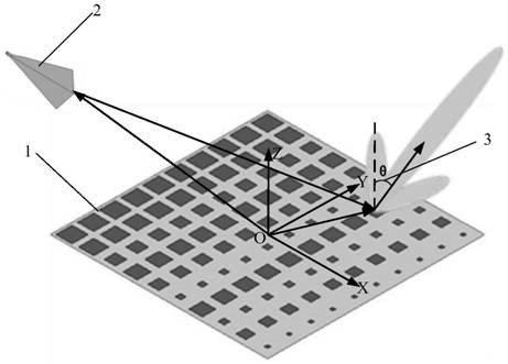
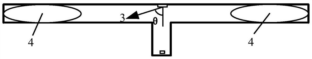
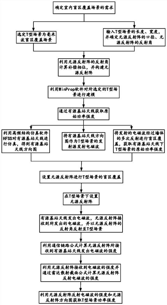
[0047] refer to figure 1 , figure 2 and image 3

[0048] Step 1. Determine the requirements of indoor blind zone coverage scenarios;

[0049] (1a), the T-shaped scene is selected as the millimeter wave blind zone coverage scene;

[0050] (2b), input the length and width of the T-shaped scene, and determine the aperture of the passive reflector array, the reflection angle 3 of the passive reflector array;

[0051] Step 2, using the reflection angle 3 of the passive reflective array to calculate the compensation phase, and constructing the passive reflective array 1;

[0052] Step 3, utilize WinProp software to model the selected T-shaped scene;

[0053] (3a), from the selected T-shaped scene, obtain the structural dimensions of the wall, door, window, ceiling and floor;

[0054] (3b), respectively carry out modeling to the material of determined wall, door, window, ceiling and floor, and obtain T-shaped scene;

[0055] Step 4, obtain the original power intensity throug...

Embodiment 2

[0087] The diameter of the passive reflector array 1 is 240mm long and 240mm wide.

[0088] The reflection angle 3 of the passive reflection array 1 is 40°-60°. The reflection angle in the present invention is 40°, which can also meet the blind spot coverage requirement.

[0089] The variation range of the compensation phase is >360°.

[0090] The frequency range of the active base station antenna 2 is 24GHz-30GHz, and the half-power lobe width of the pattern of the active base station antenna 2 is ≥20°. The operating frequency in the present invention is 24GHz, and the half-power lobe width is 40°.

[0091] The projection of the center of the active base station antenna 2 to the center of the XOY plane of the passive reflector array coincides with each other.

[0092] Said power intensity ≥ -90dBm.

Embodiment 3

[0094] The diameter of the passive reflector array 1 is 240mm long and 240mm wide.

[0095] The reflection angle 3 of the passive reflection array 1 is 40°-60°. The reflection angle in the present invention is 60°, which can also meet the blind spot coverage requirement.

[0096] The variation range of the compensation phase is >360°.

[0097] The frequency range of the active base station antenna 2 is 24GHz-30GHz, and the half-power lobe width of the pattern of the active base station antenna 2 is ≥20°. The operating frequency in the present invention is 30 GHz, and the half-power lobe width is 40°.

[0098] The projection of the center of the active base station antenna 2 to the center of the XOY plane of the passive reflector array coincides with each other.

[0099] Said power intensity ≥ -90dBm.

[0100] Below in conjunction with accompanying drawing, the simulation result of the present invention is described in further detail

[0101] refer to Figure 4 , Figure...


PUM


Abstract

The invention discloses a millimeter wave indoor passive coverage method. The millimeter wave indoor passive coverage method comprises the following steps: determining a demand of an indoor blind areacoverage scene; selecting a T-shaped scene to construct a passive reflection array; carrying out modeling on the selected T-type scene by utilizing WinProp software; taking the antenna directional diagram of the active base station as an emission source of a T-shaped scene, performing blind area coverage on the emitted electromagnetic waves through multiple reflections of a wall body, and obtaining the original power intensity of the T-shaped scene under the antenna of the active base station; setting a passive reflection array to perform blind area coverage of the T-shaped scene, and obtaining the power intensity of the T-shaped scene. The millimeter wave indoor blind area coverage method can be applied to millimeter wave indoor blind area coverage, the passive reflection array enables the power intensity of the T-shaped scene to be improved by 10 dBm compared with the original power intensity, the 40 m blind area coverage range is obtained, and blind area coverage is effectively carried out on T-shaped scenes with different lengths.

Description

technical field [0001] The invention belongs to the technical field of electromagnetic communication, in particular to an indoor passive coverage method in the technical field of wireless communication, which can be used for millimeter wave blindness compensation in the technical field of wireless communication. Background technique [0002] In a traditional communication environment, operators of wireless systems such as cellular phone systems wish to reduce signal coverage holes of base stations, which can be achieved by installing active base station coverage signal holes. However, in millimeter-wave indoor communication, due to the large attenuation and poor diffraction ability of millimeter-wave, the number of active base station deployments has increased sharply due to coverage blind spots, which has caused a surge in costs. In order to reduce the cost of deploying base stations, passive reflectarrays can be used to cover blind areas. As a passive relay, the passive r...

Claims


Application Information

Patent Timeline
Patent Type & Authority Patents(China)
IPC IPC(8): H04W16/20H04W16/26H04W16/22H04W16/30
CPCH04W16/20H04W16/225H04W16/26H04W16/30
Inventor 李龙路泽卿方遥易浩
Owner XIDIAN UNIV
Why Eureka
Try Eureka