Vacuum defoaming device and defoaming method for high-viscosity liquid

A vacuum defoaming and high-viscosity technology, applied in the defoaming field of slurry, can solve the problems of high heating energy consumption, low defoaming efficiency, and reduced defoaming efficiency, so as to increase surface tension, high defoaming efficiency, increase The effect of surface area

Pending Publication Date: 2019-08-20
SUZHOU SUNMUN TECH CO LTD
View PDF3 Cites 7 Cited by
  • Summary
  • Abstract
  • Description
  • Claims
  • Application Information

AI Technical Summary

Problems solved by technology

However, the above-mentioned defoaming methods have certain defects: the production efficiency of stirring centrifugal defoaming is low, and there are many residual bubbles; when vacuum defoaming, continuous vacuum defoaming often causes excessive expansion of bubble volume, which causes bubbles to enter the vacuum pump and affect the equipment. In the normal use of intermittent vacuuming and defoaming, the interval between two vacuumings is too long, resulting in low defoaming efficiency, and the gas released during the interval of vacuuming will affect the vacuum degree, further reducing the defoaming efficiency; film defoaming The defoaming speed is slow and the processing capacity is small; during ultrasonic defoaming, due to the large resistance of small bubbles in the high-viscosity liquid when they vibrate under the influence of ultrasonic waves, the probability of converging into large bubbles is much smaller, even if large bubbles are formed. It escapes quickly from the liquid, and the defoaming efficiency for high-viscosity liquids is extremely low; heating and defoaming not only consumes a lot of energy, but also accelerates the pigment in the water-based color paste due to factors such as the reduction of the adsorption force of the dispersant at high temperature. Settling, affecting the stability of the product
[0005] There are many existing patent reports on defoaming equipment and methods, such as the Chinese patent "Defoaming kettle and defoaming method used in the manufacture of polyamic acid resin" with application number 201410356940.4, which discloses a hemispherical thin-layer distributor. A defoaming kettle, and a jacket is installed outside the tank, and a heat-conducting medium is added to the jacket, and the polyamic acid resin solution entering the defoaming kettle disperses and flows in a thin layer, and then passes through the gap between the lower edge of the thin-layer distributor and the inner wall of the tank Keep the thin layer to continue to flow down along the inner wall of the tank, and at the same time, take advantage of the decrease in the viscosity of the liquid product and the strength of the liquid film at high temperature to destroy the stability of the bubbles, and finally gather at the bottom of the tank. Although the device has a simple structure and a good defoaming effect, it Heating consumes a lot of energy, and excessive heating during the defoaming process of some products will affect product quality; the Chinese patent "defoaming device for high-viscosity liquid products" with application number CN201010273742.3 mainly uses the thinning of slurry under high shear force It is only suitable for thixotropic slurry, such as gel pen ink and other products, not suitable for high-viscosity liquid products that do not have significant thixotropy; the US patent with the publication number US5612219 introduces a biological The defoaming device in the reactor is a plate made of hydrophobic material at an angle of 45°-90° to the liquid surface, and defoaming is carried out under stirring
The defoaming problem of high-viscosity liquid products with less thixotropy is an important problem that plagues the production of high-viscosity liquid products. For high-viscosity liquid products that do not have significant thixotropy, the defoaming equipment disclosed in the above-mentioned prior art has a high defoaming efficiency. Difficult to meet the requirements of industrial production

Method used


Image

  • Vacuum defoaming device and defoaming method for high-viscosity liquid
  • Vacuum defoaming device and defoaming method for high-viscosity liquid

Examples


Embodiment Construction

[0050] In order to be able to understand the technical means of the present invention more clearly and implement it according to the contents of the description, the specific implementation of the present invention will be further described in detail below in conjunction with the accompanying drawings and examples. The following examples are used to illustrate the present invention, but not to limit the scope of the present invention.

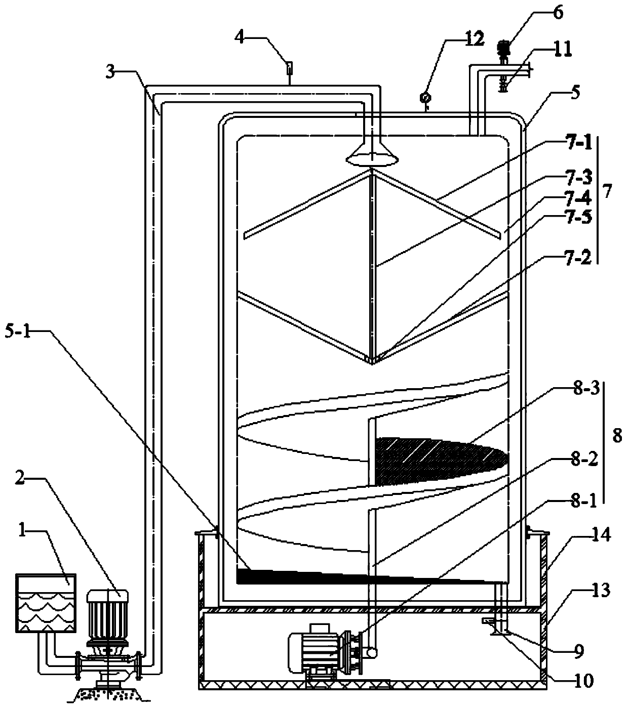
[0051] This specific example describes in detail a vacuum defoaming device for high-viscosity liquids. For the specific structure, see figure 1 shown in .

[0052] The vacuum defoaming equipment mainly includes a control device, a feeding device and a defoaming device.

[0053] control device It mainly includes input modules, central processing modules, etc. The input modules are mainly components used for inputting parameter information on human-computer interaction interfaces such as touch screens, mice, and keyboards, and the central proc...


PUM

PropertyMeasurementUnit
thicknessaaaaaaaaaa
thicknessaaaaaaaaaa

Abstract

The invention discloses a vacuum defoaming device and a defoaming method for high-viscosity liquid. The vacuum defoaming device is provided with two opposite defoaming baffles and a large-area spiralplate; so high-viscosity liquid is always in the state of a thin-film flow layer, which allows the surface area and the surface tension of the high-viscosity liquid to be greatly increased and bubblesto be effectively eliminated; and the low-speed rotation of the spiral plate accelerates the film formation speed and the flowing speed of the high-viscosity liquid, and the rotational shear force generated by the spiral plate can also eliminate bubbles. The defoaming method of the invention adopts multiple defoaming manners, and performs efficient and stable defoaming through a combination of acertain degree of vacuum, the rotating speed of the spiral plate and the flow control of feed and discharge flow valves. According to a technical scheme described in the invention, the vacuum defoaming device has the advantages of simple structure, simple operation, low energy consumption, low cost, high defoaming efficiency and the like, is suitable for defoaming of high-viscosity liquid, and canprotect high-viscosity liquid from the adverse impact of high temperature, defoaming agent and the like.

Description

technical field [0001] The invention relates to a vacuum defoaming device and a defoaming method, in particular to a vacuum defoaming device and a defoaming method for high-viscosity liquids, and is especially suitable for defoaming high-viscosity slurry containing surfactants. Background technique [0002] In the production process of high-viscosity liquids such as water-based colorants, in order to ensure that water-insoluble solid particles such as pigments can be stably dispersed in the liquid, it is often necessary to add surface-active substances such as dispersing aids, but this will lead to a large number of tiny Bubbles are generated and the generated bubbles are relatively stable, but it is difficult for high-viscosity liquids such as water-based colorants to eliminate the bubbles naturally, or it often takes a long time to naturally defoam, which has great impact on the continuous production, packaging, storage, transportation, and application of the product. have...

Claims


Application Information

Patent Timeline
Patent Type & Authority Applications(China)
IPC IPC(8): B01D19/00
CPCB01D19/0042
Inventor 杜长森徐海梅伍金平解亚楠
Owner SUZHOU SUNMUN TECH CO LTD
Why Eureka
Try Eureka