

Electro-hydraulic mix-drive sand mixing equipment
A technology of sand mixing equipment and electro-hydraulic mixing, applied in mixers, mining fluids, transportation and packaging, etc., can solve the problems of high daily maintenance costs, pollution, and large space occupation of power systems, and achieve equipment transportation and well site. Flexible and convenient layout, optimized power system configuration, small size and weight of the whole machine
- Summary
- Abstract
- Description
- Claims
- Application Information
AI Technical Summary
Problems solved by technology
Method used
Image

Examples
Embodiment Construction
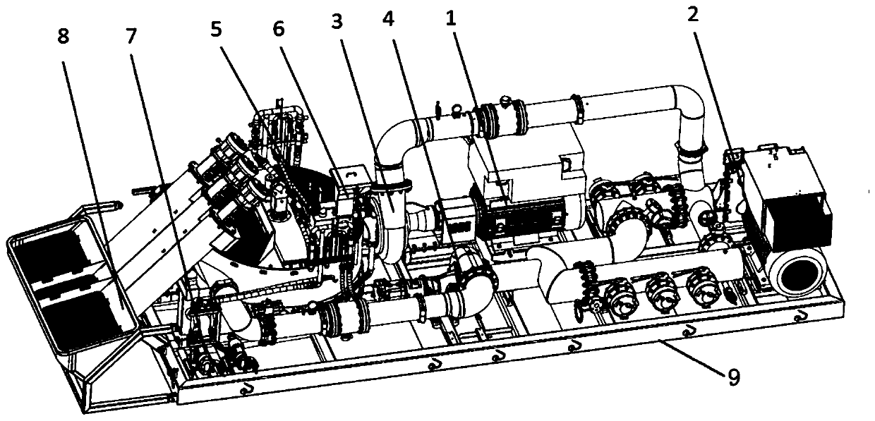
[0022] Such as figure 1 As shown, an electro-hydraulic hybrid driving sand mixing equipment includes a skid base 9, an electric motor, a hydraulic pump, a discharge centrifugal pump 3, a suction centrifugal pump 4, a mixing tank 5, a dry adding system 6, a liquid adding system 7, and a sand conveying winch Dragon system 8, suction manifold and discharge manifold, the electric motor, hydraulic pump, discharge centrifugal pump 3, suction centrifugal pump 4, mixing tank 5, dry addition system 6, liquid addition system 7, sand delivery auger system 8, The suction manifold and the discharge pipe are assembled into a skid and installed on the skid base 9. There are two motors, including the first motor 1 and the second motor 2. The first motor 1 is used to drive the discharge centrifugal pump 3, and the discharge centrifugal pump The pump 3 is directly driven by the first motor 1, which can conveniently and effectively increase the input power of the pump, thereby improving the work...
PUM
 Abstract
Description
Claims
Application Information