
Square cutting, edge cutting and polishing all-in-one machine

An all-in-one machine, grinding and polishing technology, applied in the direction of grinding/polishing equipment, grinding machines, metal processing equipment, etc., can solve the problems of inconvenient operation, high labor intensity, and a large number of operators, so as to improve grinding efficiency, The effect of reducing the grinding allowance and saving the rough grinding process

Pending Publication Date: 2019-08-23
QINGDAO GAOCE TECH CO LTD
View PDF0 Cites 3 Cited by
  • Summary
  • Abstract
  • Description
  • Claims
  • Application Information

AI Technical Summary

Problems solved by technology

[0003] At present, the cutting machines, square cutting machines, and grinding and polishing machines used in the market all process the bars with a single machine, and then manually transport them to another equipment for processing. It is necessary to frequently adjust the position of the bar and the bar, which is very inconvenient to operate. Moreover, the labor intensity is high and a large number of operators are required; with the continuous improvement of photovoltaic crystal pulling technology, the processing quality and efficiency of cutting, cutting, and grinding equipment are also getting higher and higher, and the dimensional accuracy error of the square root can be improved from ±0.3mm To within ±0.1mm, the size difference is 0.05-0.1mm, which is just the fine grinding allowance, which can save a lot of grinding amount for the next grinding process

Method used


Image

  • Square cutting, edge cutting and polishing all-in-one machine
  • Square cutting, edge cutting and polishing all-in-one machine
  • Square cutting, edge cutting and polishing all-in-one machine

Examples


Embodiment 1

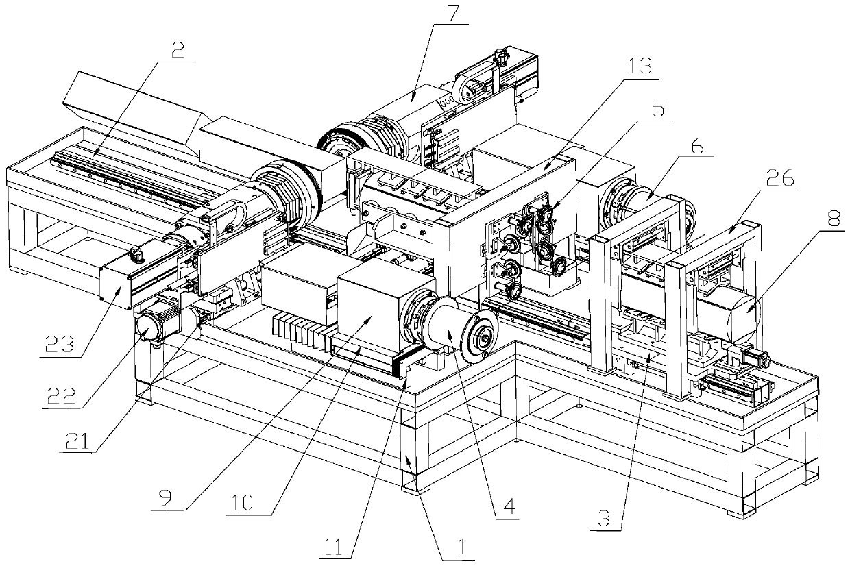
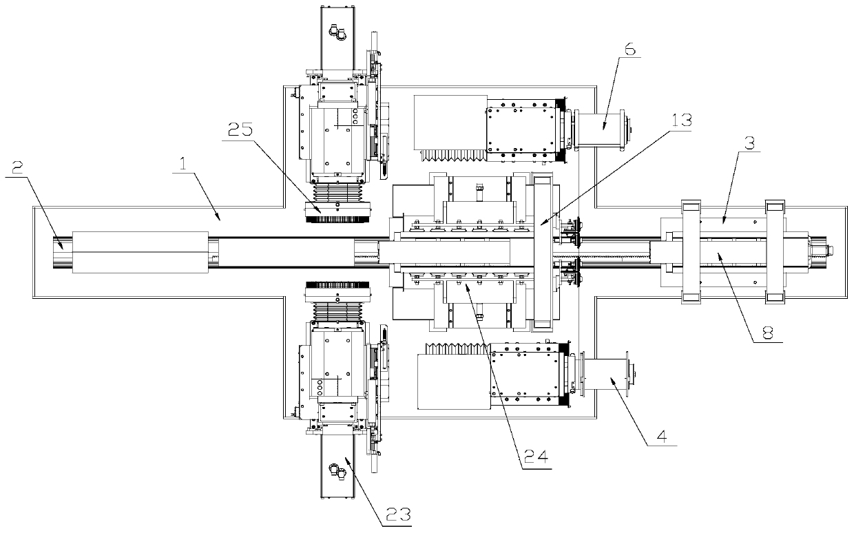
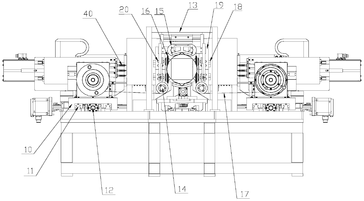
[0031] Such as Figure 1-Figure 3 As shown, an integrated machine for cutting square, edge cutting, grinding and polishing includes a base 1, on which a slide rail 2 is provided, and on the slide rail 2 is sequentially provided with a loading table along the transmission direction of the crystal silicon 8. The mechanism 3, the centering mechanism 26, the square prescribing mechanism, the edge-cutting mechanism 24, and at least two grinding and polishing mechanisms 7, that is to say, the all-in-one machine can combine prescribing and grinding processes, and the crystalline silicon 8 can be squared Grinding and polishing to the edge and corner processing, processing and shaping at one time, saving the rough grinding process, you can directly enter the slicing process.

[0032] Such as Figure 4 with Figure 5 As shown, the loading table mechanism 3 is used to carry the crystalline silicon 8 and drive the crystalline silicon 8 to move along the slide rail 2. Specifically, the loadin...

Embodiment 2

[0036] Such as figure 1 with Figure 5 As shown, the centering mechanism 26 includes a centering bracket 37, a parallel jaw cylinder 38, and a clamping plate 39. The centering bracket 37 is arranged along a vertical direction, and the bottom of the centering bracket 37 is fixedly connected to the base 1. The jaw cylinder is arranged along the direction perpendicular to the slide rail 2, the cylinder end is fixedly connected with the centering bracket 37, and the piston end is connected with the clamping plate 39 which is arranged along the vertical direction. Both the parallel jaw cylinder 38 and the clamping plate 39 are arranged symmetrically, and the clamping plate is attached to the cut surface of the crystal silicon 8.

[0037] At least one centering mechanism 26 is provided along the length direction of the crystalline silicon 8. In this embodiment, there are two centering mechanisms 26. Along with the extension or retraction of the parallel jaw cylinder 38, the clamping p...

Embodiment 3

[0039] Such as figure 1 with image 3 As shown, the square-opening mechanism includes a pay-off drum 4, a take-up drum 6 and a square wire net 5. The cutting wire 17 bypasses the square wire net 5 and is enclosed for the crystalline silicon 8 to pass through and cut the side skin of the crystalline silicon 8 and Angular cutting channel, and the cutting line is parallel. In this embodiment, the cutting wire 17 uses, but is not limited to, a loop wire or an ultra-fine diamond wire to realize high-precision square extraction, ensure the size and surface quality, and facilitate the processing of the crystalline silicon 8 through rapid grinding. The pay-off drum 4 and the take-up drum 6 are both arranged in parallel along the sliding rail 2. At the same time, the pay-off reel 4 and the take-up reel 6 are provided with a winding drive assembly and a winding drive assembly. The winding drive assembly is used to drive the pay-off reel 4 or the reel 6 to rotate. The wire drive assembly...


PUM

PropertyMeasurementUnit
lengthaaaaaaaaaa

Abstract

The invention relates to a square cutting, edge cutting and polishing all-in-one machine, and belongs to the technical field of crystalline silicon machining equipment. The all-in-one machine comprises a base, wherein a sliding rail is arranged on the base, a feeding workbench mechanism, a centering mechanism, a squaring mechanism, a scrap edge falling mechanism and at least two polishing mechanisms are sequentially arranged on the sliding rail along the conveying direction of crystalline silicon, the feeding workbench mechanism is used for bearing the crystalline silicon and driving the crystalline silicon to move along the sliding rail, cutting lines bypass a squaring net of the squaring mechanism and form parallel lines, the scrap edge falling mechanism is used for sucking scrap edges generated under the cutting of the squaring mechanism, and the at least two polishing mechanisms are symmetrically arranged along the sliding rail. According to the all-in-one machine, the squaring mechanism and the polishing mechanism are integrated into one, and the crystal silicon can directly enter the slicing process after being machined at one time; the squaring mechanism adopts a form of two-wire squaring, so that cutting the crystal silicon into square bars and removing edges and corners are realized, the grinding allowance of the grinding procedure is reduced, and the rough grinding procedure is omitted; and a crystal bar is subjected to edge and corner machining immediately following one-time polishing after cut into the square bars, so that the grinding efficiency is remarkably improved.

Description

Technical field [0001] The invention belongs to the technical field of crystalline silicon processing equipment, and specifically relates to an integrated machine for cutting square cutting edge grinding and polishing. Background technique [0002] The manufacturing process of silicon wafers used in the production of solar panels is divided into several steps: crystal pulling, cutting, square extraction, grinding, and slicing. Crystal pulling is to generate cylindrical single crystal silicon rods by chemical deposition in a crystal pulling furnace with a length of up to 6 meters; truncation refers to cutting the pulled single crystal silicon rods into different lengths (100~700mm ); square rooting refers to cutting the truncated single crystal silicon rods of different lengths into a rectangular parallelepiped shape; grinding down refers to grinding and polishing the four surfaces of the rectangular parallelepiped silicon single crystal rods with an abrasive tool, and The proces...

Claims


Application Information

Patent Timeline
Patent Type & Authority Applications(China)
IPC IPC(8): B28D5/04B28D7/04B28D7/00B24B27/00
CPCB28D5/045B28D5/0082B28D5/0058B24B27/0076B24B27/0092
Inventor 解培玉段景波徐公志王丹王宝超于秀升
Owner QINGDAO GAOCE TECH CO LTD
Learn More