Wide-Angle Scanning Anamorphic Hemispherical Dielectric Lens Antenna Based on Array Feed

A dielectric lens antenna and dielectric lens technology, which is applied to antennas, antenna arrays, specific array feeding systems, etc., can solve the problems of small scanning angle, reduced antenna profile, and high overall antenna profile, so as to improve scanning angle and aperture efficiency. The effect of low and high bore efficiency

Active Publication Date: 2020-01-10
UNIV OF ELECTRONICS SCI & TECH OF CHINA
View PDF7 Cites 0 Cited by
  • Summary
  • Abstract
  • Description
  • Claims
  • Application Information

AI Technical Summary

Problems solved by technology

The antenna uses a uniform dielectric column as the lens, and its antenna aperture efficiency is low. Although it realizes a 360° omnidirectional scanning of a surface by switching the beam, the difficulty of integrating the arc-shaped feed array is also an obvious shortcoming.
In 2015, Liu Yanhui of Xiamen University and others proposed a multi-beam planar patch lens antenna in the patent CN 103050782B. The antenna realized the multi-beam lens antenna in the form of a planar patch array, although the aperture efficiency reached 84%. , but the overall profile of the antenna is relatively high, multi-beam scanning is realized through the deflection of the horn feed and the scanning angle is less than ±30°
In the current research, flat panel and hemispherical lens antennas still have the problem of small scanning angles
In 2014, Carolina Mateo-Segura et al. published an article titled "FlatLuneburg Lens via Transformation Optics for Directive Antenna Applications" in IEEE transactions on antennas and propagation, vol.62, no.4, using transformation optics for ball dragons The Luneberg lens is compressed into a flat Luneberg lens, which not only retains the inherent excellent focusing characteristics of the Luneberg lens, but also effectively reduces the profile of the antenna, but the antenna can only scan to ±34° by switching the beam
In 2016, N.T.Nguyen et al published an article titled "Improvement of the Scanning Performance of the Extended Hemispherical Integrated Lens Antenna Using a Double Lens Focusing System" in IEEE transactions on antennas and propagation, vol.64, no.8, A double-lens focusing system, that is, a hemispherical lens + a semi-convex lens, is used to twist the original arc-shaped front of the feed into a plane for easy integration with the planar feed array. However, this method sacrifices the antenna profile and the final scan of the antenna The angle is also only ±30°
In 2018, Feng Pengyu et al. published an article titled "Ku-Band Transmitarrays With Improved Feed Mechanism" in IEEE transactions on antennas and propagation, vol.66, no.6, and proposed a dipole using 4×4 Metamaterial transmission array antenna fed by sub-antenna array, this feeding mechanism effectively reduces the overall profile of the antenna, but the article does not involve beam scanning
Although in this article, due to the use of a passive phased array with a feed phase-shifting network for the convenience of experimental verification, the EIRP of the antenna has not been improved, but if the active phased array is used as the feed antenna, the EIRP of the antenna got a huge boost

Method used


Image

  • Wide-Angle Scanning Anamorphic Hemispherical Dielectric Lens Antenna Based on Array Feed
  • Wide-Angle Scanning Anamorphic Hemispherical Dielectric Lens Antenna Based on Array Feed
  • Wide-Angle Scanning Anamorphic Hemispherical Dielectric Lens Antenna Based on Array Feed

Examples


Embodiment Construction

[0023] specific implementation plan

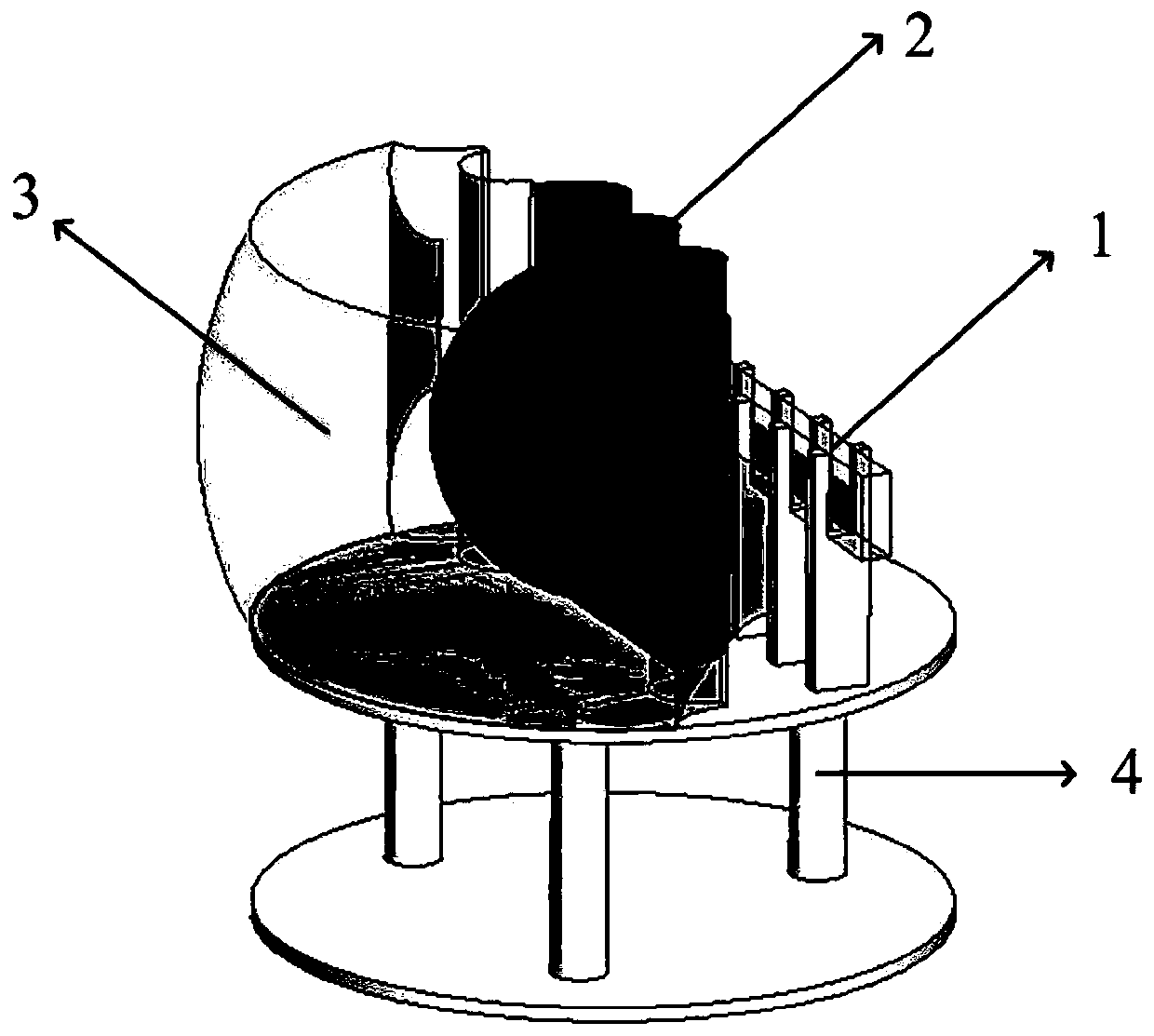
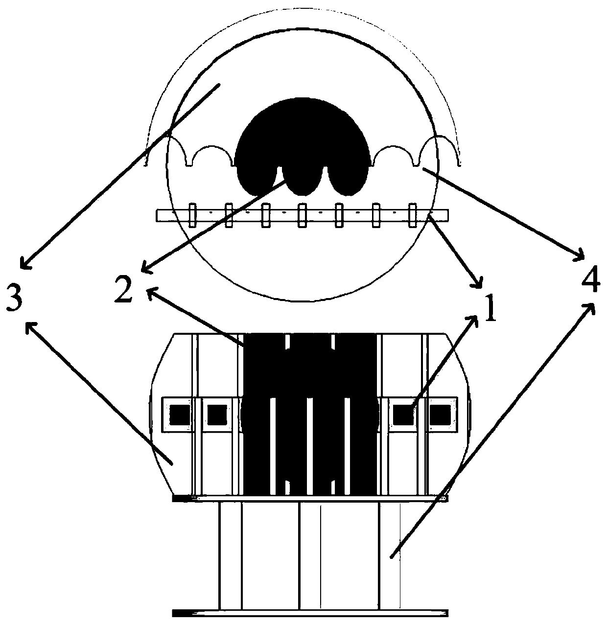
[0024] figure 1 and figure 2 The three-dimensional design structure of the deformed hemispherical dielectric lens antenna based on array feeding is described exemplarily. As shown in the figure, this structure includes a 1×8 square microstrip patch feed source array 1 , an inner layer 2 of a deformed hemispherical dielectric lens, an outer layer 3 of a deformed hemispherical dielectric lens, and an antenna support firmware 4 . Among them, the 1×8 square microstrip patch feed source array 1, the inner layer 2 of the anamorphic hemispherical dielectric lens, the outer layer 3 of the anamorphic hemispherical dielectric lens, are in the same horizontal plane, the inner layer 2 of the anamorphic hemispherical dielectric lens and the outer layer 3 of the anamorphic hemispherical dielectric lens Connected together to form a complete deformed hemispherical dielectric lens, the antenna support firmware 4 supports and fixes the 1×8 square microst...


PUM


Abstract

The invention discloses a deformed hemispherical dielectric lens antenna based on array feeding for multi-beam directional communication and beam scanning. Its basic structure includes 1×8 square microstrip patch feed array, layered deformed hemispherical dielectric lens and antenna support firmware. The anamorphic lens antenna uses the method of ray optics to design the inner and outer layers of the anamorphic lens. With the form of array feeding, it effectively solves the shortcomings of the traditional hemispherical lens with small scanning angle and low EIRP, and is helpful for anamorphic hemispheres. Lens antennas are better used in long-distance multi-beam directional communication and beam scanning, low-profile usage scenarios and corresponding market demands. Using today's mature 3D printing technology, deformable lenses and antenna support firmware can be easily processed, which solves the ubiquitous engineering realization problems of lens antennas. Based on the basic structure of the present invention, other specific implementations of the present invention can be formed by reasonably changing the size and deformation of the filling medium and the form of the feed source.

Description

[0001] The invention belongs to the technical field of antennas, and relates to a deformable dielectric lens antenna, specifically a deformable hemispherical dielectric lens antenna based on an array feeding form for multi-beam directional communication and beam fast electrical scanning, especially suitable for working in the millimeter wave frequency band , low-profile and wide-angle beam scanning usage scenarios. Background technique [0002] Due to the urgent demand for multi-beam antennas in the fields of ship navigation, satellite communication, electronic countermeasures and target tracking, multi-beam antennas with high gain, narrow beam, wide scanning angle, high-speed scanning and low manufacturing cost have been paid more attention. In recent years, in order to meet larger coverage and longer communication distance, the antenna system must have high gain, high EIRP characteristics and wide beam coverage. Based on the above requirements, the present invention designs ...

Claims


Application Information

Patent Timeline
Patent Type & Authority Patents(China)
IPC IPC(8): H01Q1/38H01Q1/50H01Q19/06H01Q21/00H01Q1/12
CPCH01Q1/12H01Q1/38H01Q1/50H01Q19/06H01Q21/0006
Inventor 杨仕文刘坤宁肖仕伟陈晨陈益凯屈世伟
Owner UNIV OF ELECTRONICS SCI & TECH OF CHINA
Why Eureka
Try Eureka