Preparation method of distributed Bragg reflector and vertical cavity surface emitting laser

A technology of Bragg reflector and refractive index layer, which is applied to lasers, laser components, semiconductor lasers, etc., can solve problems such as wafer warping, and achieve the effect of avoiding wafer warping and suppressing the occurrence of reverse domains

Inactive Publication Date: 2019-08-23
度亘核芯光电技术(苏州)有限公司
View PDF11 Cites 7 Cited by
  • Summary
  • Abstract
  • Description
  • Claims
  • Application Information

AI Technical Summary

Problems solved by technology

[0004] Therefore, the technical problem to be solved by the present invention is to overcome the defects in the prior art that large-scale epitaxial wafers are prone to wafer warpage caused by the lattice constant of AlGaAs being greater than that of the GaAs substrate, thereby providing a distributed Bragg reflector Preparation method and vertical cavity surface emitting laser

Method used


Image

  • Preparation method of distributed Bragg reflector and vertical cavity surface emitting laser
  • Preparation method of distributed Bragg reflector and vertical cavity surface emitting laser
  • Preparation method of distributed Bragg reflector and vertical cavity surface emitting laser

Examples


preparation example Construction

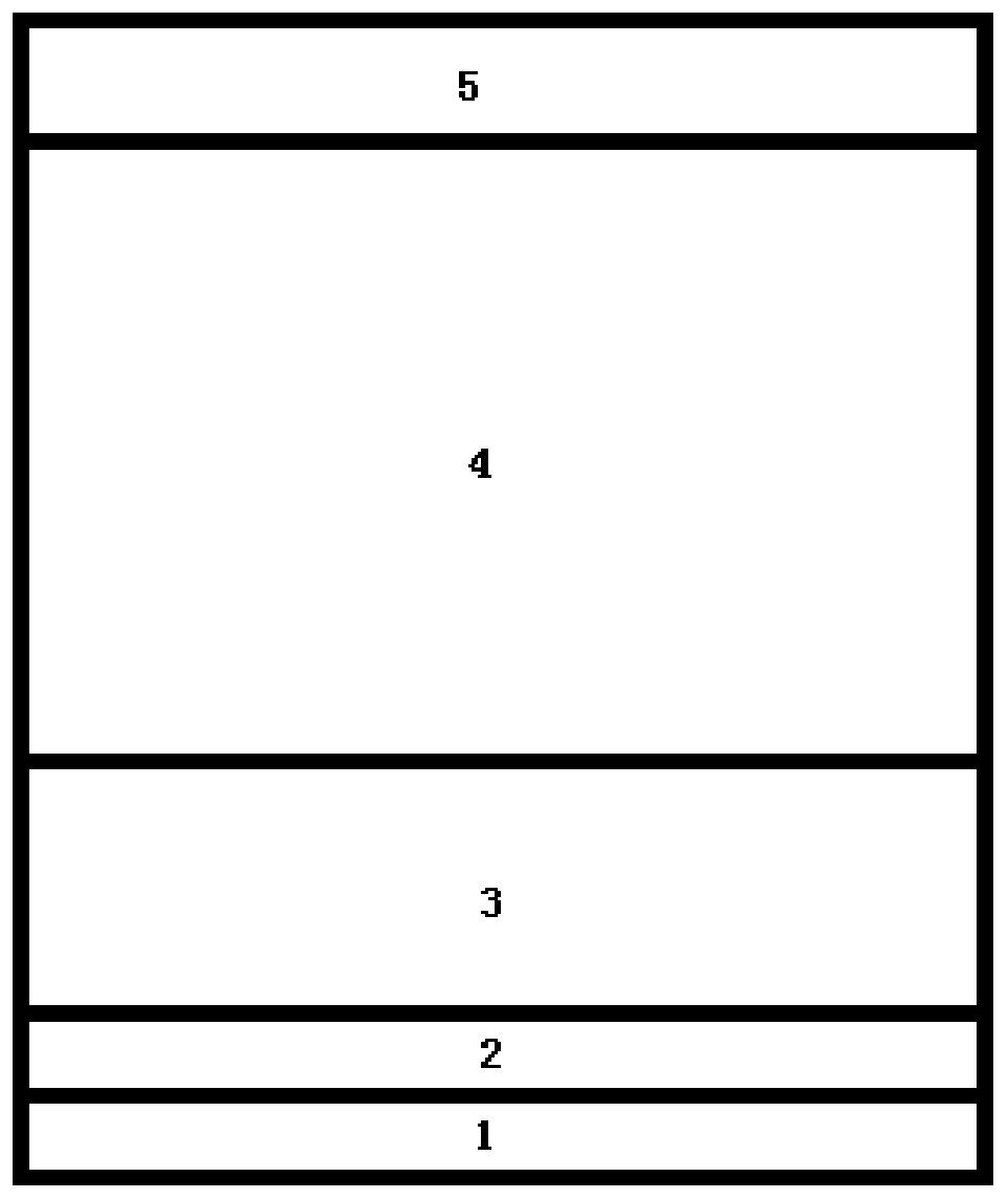
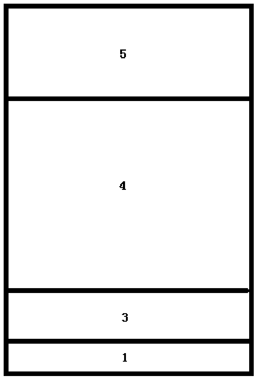
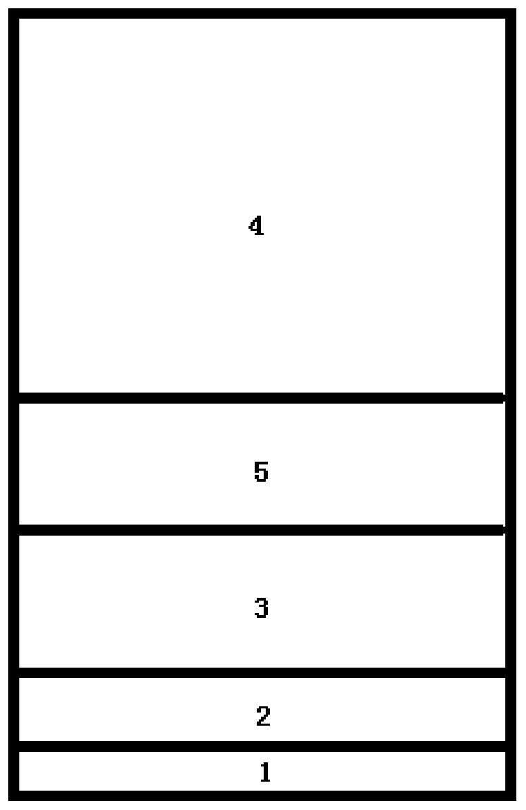
[0039] The preparation method of the distributed Bragg reflector in the embodiment of the present invention is as follows,

[0040] S1. Provide substrate;

[0041] The substrate can be Ge or In 0.01 Ga 0.99 As, Al 0.57 Ga 0.43 As, Ga 0.5 In 0.5 One of P, the embodiment uses In 0.01 Ga 0.99 As an example;

[0042] S2. Alternate growth of N to Al x Ga 1-x As is the first refractive index layer of the material, Al y Ga 1-y As is the second refractive index layer of material.

[0043] The materials of the substrate, the first refractive index layer and the second refractive index layer of the present invention are not limited thereto, and can also be other materials, as long as the lattice constant of the substrate is guaranteed to be within the lattice constant of the first refractive index layer. and the lattice constant of the second refractive index layer.

[0044] The present invention adopts a substrate whose lattice constant is between the lattice constants of...

Embodiment 1

[0048] This embodiment provides a method for preparing a distributed Bragg reflector, taking x=0.90, y=0.15, and N=25, as follows:

[0049] (1) Determine the thickness of each layer:

[0050] Using ellipsometer to test the refractive index of the material at 940nm wavelength, Al 0.9 Ga 0.1 The refractive index of As is 3.028, Al 0.15 Ga 0.85 As is 3.466, use the formula d=λ / 4n to get Al 0.9 Ga 0.1 The thickness of As is 77.61nm, Al 0.15 Ga 0.85 The thickness of As is 67.80nm. The lattice constant of the substrate Ge is Al 0.9 Ga 0.1 As layer is Al 0.15 Ga 0.85 As layer is Nucleation layer Ga 0.50 In 0.50 P is In 0.01 Ga 0.99 As buffer layer is As, the stress compensation layer Ga 0.47 In 0.53 P is Using N×(77.62×0.002−67.8×0.004)+D×0.014+0.002×100−0.001×500=0, the thickness D of the strain compensation layer is 228.54 nm.

[0051] (2) Distributed Bragg reflectors grown on Ge substrates:

[0052] Sequential epitaxial growth of 100nm Ga from Ge sub...

Embodiment 2

[0056] This embodiment provides a method for preparing a distributed Bragg reflector, taking x=0.08, y=0.95, and N=35 as follows:

[0057] (1) Determine the thickness of the DBR layer and the thickness of the stress compensation layer:

[0058] Using ellipsometer to test the refractive index of the material at 940nm wavelength, Al x Ga 1-x The refractive index of As is 3.507, Al y Ga 1-y As is 2.999, use the formula d=λ / 4n to get Al x Ga 1-x The thickness of As is 67.02nm, Al y Ga 1-y The thickness of As is 78.36nm. Substrate In 0.01 Ga 0.99 The lattice constant of As is Al x Ga 1-x As layer is Al y Ga 1-y As layer In 0.01 Ga 0.99 As buffer layer is Stress compensation layer Ga 0.55 In 0.45 P is Using N×(78.36×0.004−67.02×0.003)−D×0.018=0, it can be known that the thickness D of the strain compensation layer is 218.52 nm.

[0059] (2) Growth In 0.01 Ga 0.99 Distributed Bragg reflectors on As substrates:

[0060] by In 0.01 Ga 0.99 Sequential ep...


PUM


Abstract

The invention relates to the technical field of semiconductor lasers, and particularly discloses a preparation method of a distributed Bragg reflector and a vertical cavity surface emitting laser. Themethod comprises the steps: providing a substrate; and alternately growing the first refractive index layer and the second refractive index layer of the distributed Bragg reflector on the substrate in turn, wherein the lattice constant of the substrate is located between the lattice constant of the first refractive index layer and the lattice constant of the second refractive index layer. The substrate having the lattice constant between the lattice constant of the first refractive index layer and the lattice constant of the second refractive index lay is used so that the stress of the firstrefractive index layer and the second refractive index layer grown on the substrate is enabled to cancel each other, i.e. the stress caused by lattice mismatch is eliminated by using the strain compensation mode so that the growth of the strain-free Bragg reflector is realized, and the problem of warping of the epitaxial wafer is avoided.

Description

technical field [0001] The invention relates to the technical field of semiconductor lasers, in particular to a method for preparing a distributed Bragg reflector and a vertical cavity surface emitting laser. Background technique [0002] Vertical cavity surface emitting laser (Vertical Cavity Surface Emitting Laster, referred to as VCSEL) has small size, low threshold current, high modulation rate, high beam quality, easy to achieve single-mode operation, good temperature stability of wavelength, and low power consumption , low manufacturing cost, easy integration with other optoelectronic devices and other advantages are widely used in optical communication, optical interconnection, optical storage and other fields. [0003] The resonant cavity is one of the main conditions for generating laser light, and a distributed Bragg reflector (Distributed Bragg Reflector, DBR for short) is generally used in the VSCEL to form the resonant cavity. DBR achieves strong reflection of ...

Claims


Application Information

Patent Timeline
Patent Type & Authority Applications(China)
IPC IPC(8): H01S5/183H01S5/187
CPCH01S5/18361H01S5/187H01S2304/02
Inventor 赵勇明杨国文张艳春赵卫东
Owner 度亘核芯光电技术(苏州)有限公司
Why Eureka
Try Eureka