
A bus voltage fluctuation compensation method for vector control of permanent magnet synchronous motor without electrolytic capacitor

A permanent magnet synchronous motor, bus voltage technology, applied in the direction of motor generator control, electronic commutation motor control, motor control, etc., can solve the problems of low precision, complex control, large calculation amount, etc., and achieve small calculation amount , Wide range of applications, and the effect of reducing system costs

Active Publication Date: 2021-01-01
杭州领芯微电子有限公司
View PDF5 Cites 1 Cited by
  • Summary
  • Abstract
  • Description
  • Claims
  • Application Information

AI Technical Summary

Problems solved by technology

[0003] In order to overcome the shortcomings of the existing permanent magnet synchronous motor control method without electrolytic capacitors, which have a large amount of calculation, complicated control and low precision, the present invention provides a method that can be realized in the case of permanent magnet synchronous motor drivers without electrolytic capacitors. Effective voltage compensation methods to improve the steady-state performance of the control system, methods to suppress phase current amplitude and torque ripple

Method used


Image

  • A bus voltage fluctuation compensation method for vector control of permanent magnet synchronous motor without electrolytic capacitor
  • A bus voltage fluctuation compensation method for vector control of permanent magnet synchronous motor without electrolytic capacitor
  • A bus voltage fluctuation compensation method for vector control of permanent magnet synchronous motor without electrolytic capacitor

Examples


Embodiment Construction

[0031] The present invention will be further described below in conjunction with the accompanying drawings.

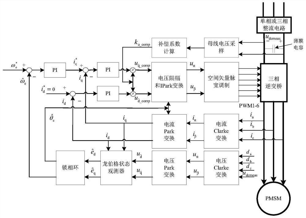
[0032] refer to figure 1 , a position sensorless control voltage compensation method for a permanent magnet synchronous motor without an electrolytic capacitor, which can achieve better steady-state performance when the permanent magnet synchronous motor driver has no busbar electrolytic capacitor, comprising the following steps:

[0033] Step 1. Detect the bus voltage, and calculate the voltage compensation coefficient k according to the real-time detected bus voltage and its changing law u_comp ,

[0034]

[0035] In the formula, U dcreal is the ideal bus voltage, U dcmeas is the bus voltage detected in real time;

[0036] Step 2, calculate the output phase voltage by detecting the bus voltage and the three-phase duty cycle,

[0037]

[0038] In the formula, d a 、d b 、d c are the three-phase duty cycle;

[0039] Then project the three-phase voltage ont...


PUM


Abstract

A vector control bus voltage fluctuation compensation method for a permanent magnet synchronous motor without an electrolytic capacitor comprises the following steps: firstly, detecting the magnitudeand fluctuation rule of a bus voltage in real time through a bus voltage detection module, and calculating a voltage compensation coefficient; meanwhile, calculating and outputting a three-phase voltage through the bus voltage and a three-phase duty ratio, carrying out the Clarke conversion and Park conversion to obtain a direct-axis (d-axis) voltage and a quadrature-axis (q-axis) voltage under arotating coordinate system; and finally compensating for the d-axis voltage and the q-axis voltage according to the calculated voltage compensation coefficient. Aiming at the problems of three-phase current amplitude fluctuation, current harmonic increase and the like caused by bus voltage fluctuation in a bus-free electrolytic capacitor occasion of a driver, the method improves the steady-state performance of a control system, and inhibits the phase current amplitude and the torque ripple.

Description

technical field [0001] The invention belongs to the technical field of permanent magnet synchronous motor control, and relates to a method for compensating bus voltage fluctuation of a permanent magnet synchronous motor without electrolytic capacitor vector control. Background technique [0002] Permanent magnet synchronous motors use permanent magnets instead of excitation windings, which have the advantages of high power density, large torque inertia ratio, and high efficiency. Therefore, they are widely used in many fields such as servo systems, household appliances, and electric vehicles. The vector control of the permanent magnet synchronous motor requires the coordinate transformation of the rotor position information. The traditional method uses a mechanical position sensor to obtain the rotor position, which leads to problems such as increased cost and increased volume and weight of the motor. At the same time, in order to make the bus voltage more stable, the tradit...

Claims


Application Information

Patent Timeline
IPC IPC(8): H02P21/00H02P21/14H02P25/098
CPCH02P21/0003H02P21/14H02P2207/05H02P25/098
Inventor 吴春黄希钟德刚
Owner 杭州领芯微电子有限公司
Learn More