Drilling device with gas extraction hole radius adjustable while drilling and working method thereof
A gas extraction and drilling device technology, applied in drilling equipment and methods, drill bits, drill pipes, etc., can solve the problems of misjudgment of extraction effect, blind area of drilling and extraction, long extraction time, etc. Gas content and the effect of eliminating blind spots in drainage
- Summary
- Abstract
- Description
- Claims
- Application Information
AI Technical Summary
Problems solved by technology
Method used
Image
Examples
Embodiment 1
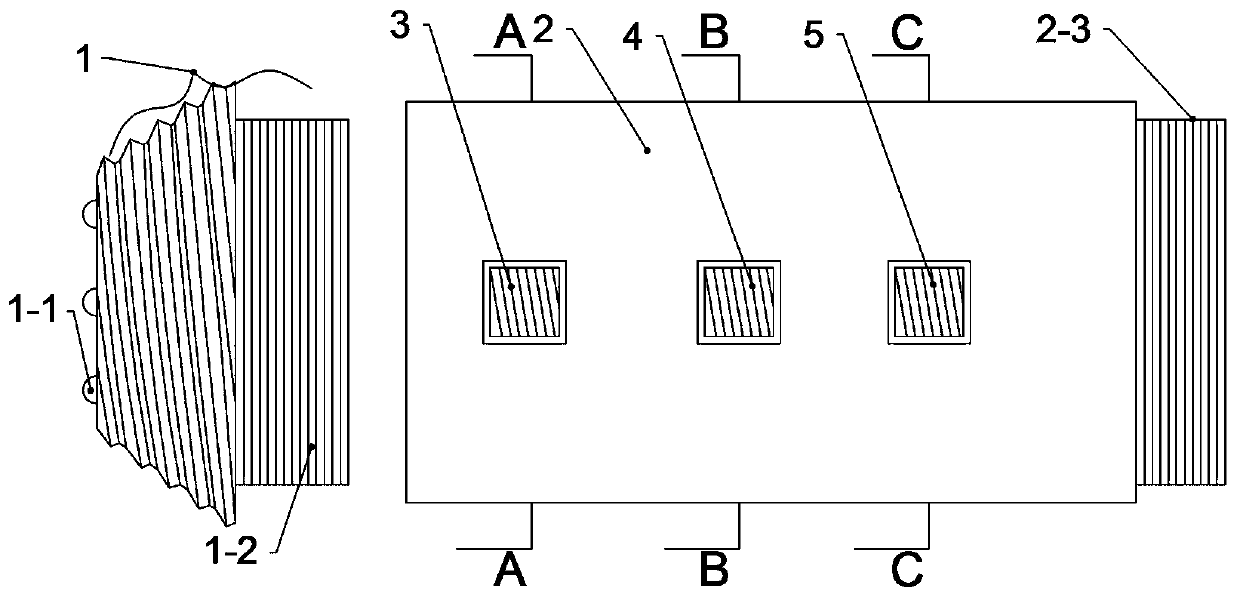
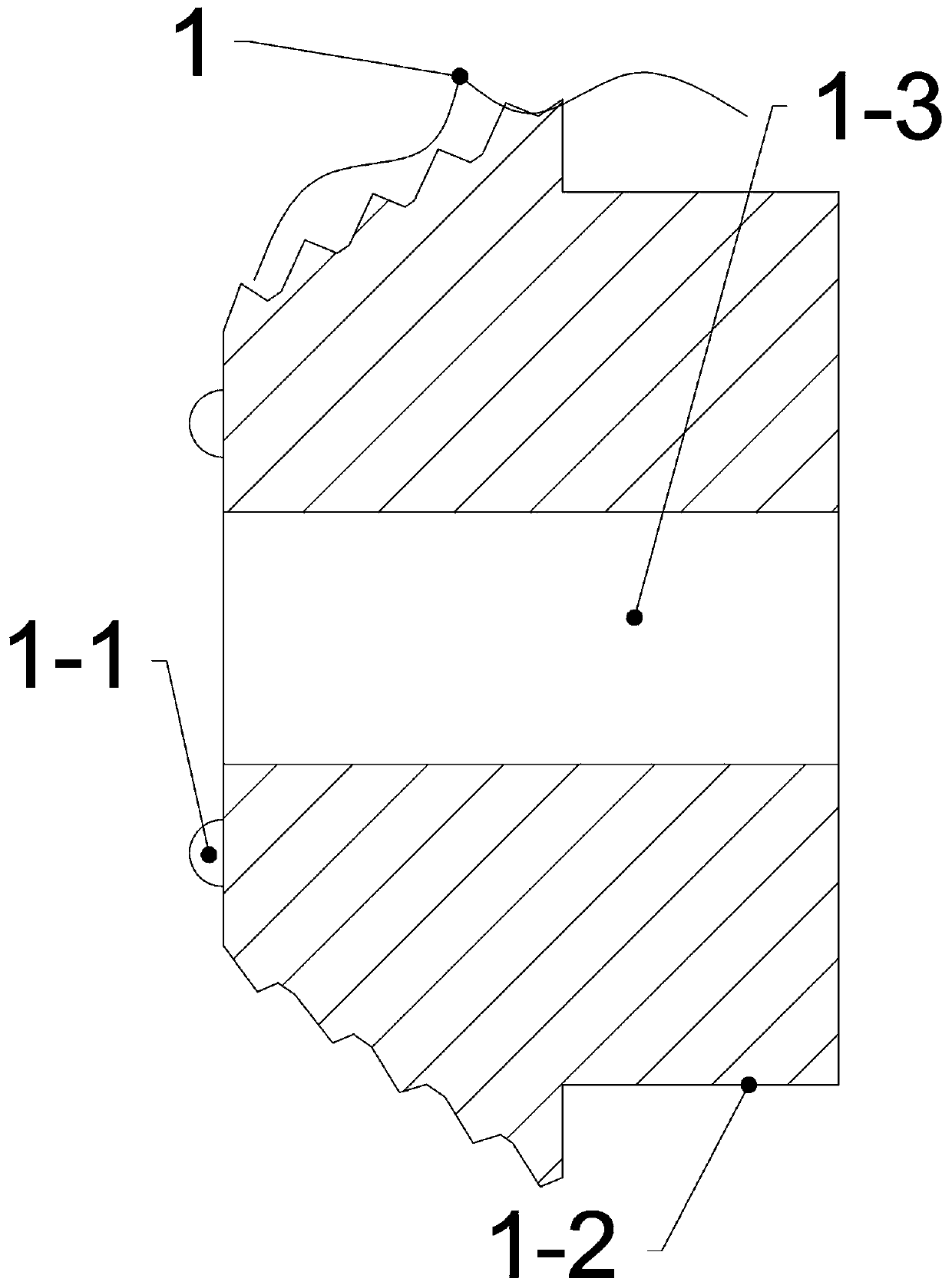
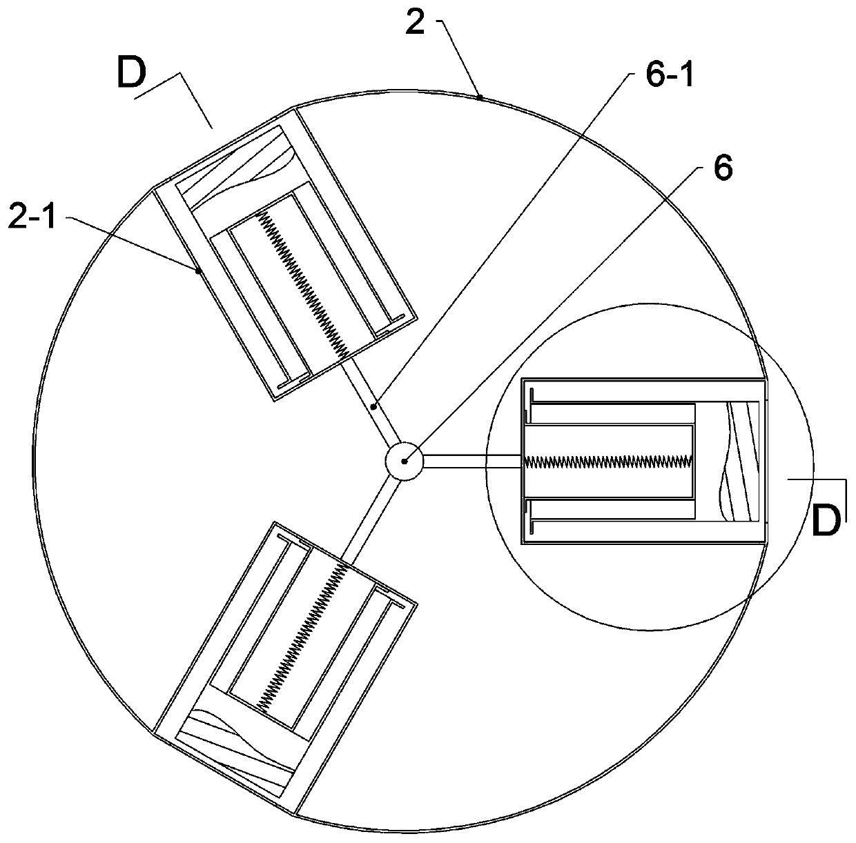
[0052] Embodiment 1, a gas drainage hole radius adjustable drilling device, such as Figure 1-4 , including a drill bit 1 and a drill pipe 2 connected together, one end of the drill bit 1 is provided with annular uniformly distributed drill teeth 1-1, the other end is a threaded connecting pipe 1-2, the middle part of the drill bit 1 is a cone and the surface is provided with Including radial teeth, the drill pipe 2 is a hollow pipe structure, the center of the drill bit 1 is provided with a water outlet hole 1-3 communicating with the drill pipe 2, one end of the drill pipe 2 is provided with internal thread I2-4, and the other end is provided with a threaded nozzle Ⅰ2-3, the threaded connecting pipe 1-2 cooperates with the internal thread Ⅰ2-4 of the drill pipe 2, and the surface of the drill pipe 2 is provided with at least one set of ring-shaped and concave bracket grooves 2-1, and the bracket grooves 2- 1 is placed with a bracket body, the notch of the bracket groove 2-1 ...
Embodiment 2
[0054] Embodiment two is basically the same as embodiment one, the difference is: as Figure 1-9 , there are three sets of bracket grooves 2-1 on the surface of the drill pipe 2, and the three groups of bracket grooves 2-1 are arranged in sequence from left to right, and the first bracket body 3, the second bracket body 4, and the first bracket body 4 are placed in sequence. Three brackets 5, the bracket baffle below the first bracket 3 is turned outwards and is the first bracket 3-1, the first bracket 3-1 and its corresponding notch baffle 2-2 cooperation; the bracket baffle below the second bracket 4 is turned inward and is the second bracket baffle 4-1, and the tubular structure of the second bracket 4 is provided with a The primary extension tube 8, the top of the primary extension tube 8 is provided with a first extension baffle 8-1 that is turned outward, and the bottom is provided with a second extension baffle 8-2 that is turned outward, and the first extension The ba...
Embodiment 3
[0056] Embodiment three is basically the same as embodiment two, the difference is: as Figure 10 and 11 , the gas injection pipe 6 includes a base pipe 6-2 and an extension pipe 6-3, one end of the base pipe 6-2 is closed, the other end is open and provided with internal thread II 6-8, both ends of the extension pipe 6-3 are open and one end It is threaded pipe port Ⅱ6-9, and the other end is internal thread Ⅱ6-8. The internal thread Ⅱ6-8 of the base pipe 6-2 is matched with the threaded pipe port Ⅱ6-9. There are multiple extension pipes 6-3, and every two phases The adjacent extension pipe 6-3 is connected through the threaded nozzle II 6-9 and the internal thread II 6-8, the base pipe 6-2 and the extension pipe 6-3 are equipped with a self-sealing gas injection system, and the self-sealing gas injection system includes a The filling and deflation valve 6-7, the sealing structure positioned at the rear, the sealing structure includes a plugging ball 6-4 positioned at the ce...
PUM
 Abstract
Description
Claims
Application Information
 - R&D
- Intellectual Property
- Life Sciences
- Materials
- Tech Scout
- Unparalleled Data Quality
- Higher Quality Content
- 60% Fewer Hallucinations
Browse by: Latest US Patents, China's latest patents, Technical Efficacy Thesaurus, Application Domain, Technology Topic, Popular Technical Reports.
© 2025 PatSnap. All rights reserved.Legal|Privacy policy|Modern Slavery Act Transparency Statement|Sitemap|About US| Contact US: help@patsnap.com


