Grate-rotary kiln pellet flue gas ultra-low emission system

An emission system and rotary kiln technology, applied in gas treatment, combined device, membrane technology, etc., can solve the problems of denitrification efficiency, production load impact, unstable NOx emissions, low denitrification and desulfurization efficiency, etc., and achieve stable operation and equipment. Simple, low operating costs

Pending Publication Date: 2019-08-30
江苏盐环实业有限公司
View PDF0 Cites 5 Cited by
  • Summary
  • Abstract
  • Description
  • Claims
  • Application Information

AI Technical Summary

Problems solved by technology

From the point of view of the existing desulfurization system of the domestic grate-rotary kiln pellet plant, due to the insufficient desulfurization capacity of the design, there is still a certain gap between the desulfurization capacity of the desulfurization system currently in operation and the ultra-low emission requirements. If the pellet plant adopts For wet desulfurization, the "white dragon" phenomenon will appear at the end of the chimney, which will affect the aesthetics of the environment; the denitrification efficiency of the current grate-rotary kiln pellet plant denitrification system will be affected due to the increase in production load, and the NOx emissions will be unstable. Therefore, grate machine-rotary kiln pellet production enterprises urgently need to build a suitable denitrification process to meet the ultra-low emission standards required by environmental protection; and in actual construction projects, desulfurization and denitrification devices are generally installed next to each other. Warming up and running again, which increases the operating cost
[0004] In the existing grate machine-rotary kiln pellet flue gas discharge system technology, there are problems such as low efficiency in denitrification, desulfurization, dust removal, and white elimination

Method used


Image

  • Grate-rotary kiln pellet flue gas ultra-low emission system
  • Grate-rotary kiln pellet flue gas ultra-low emission system
  • Grate-rotary kiln pellet flue gas ultra-low emission system

Examples


Embodiment 1

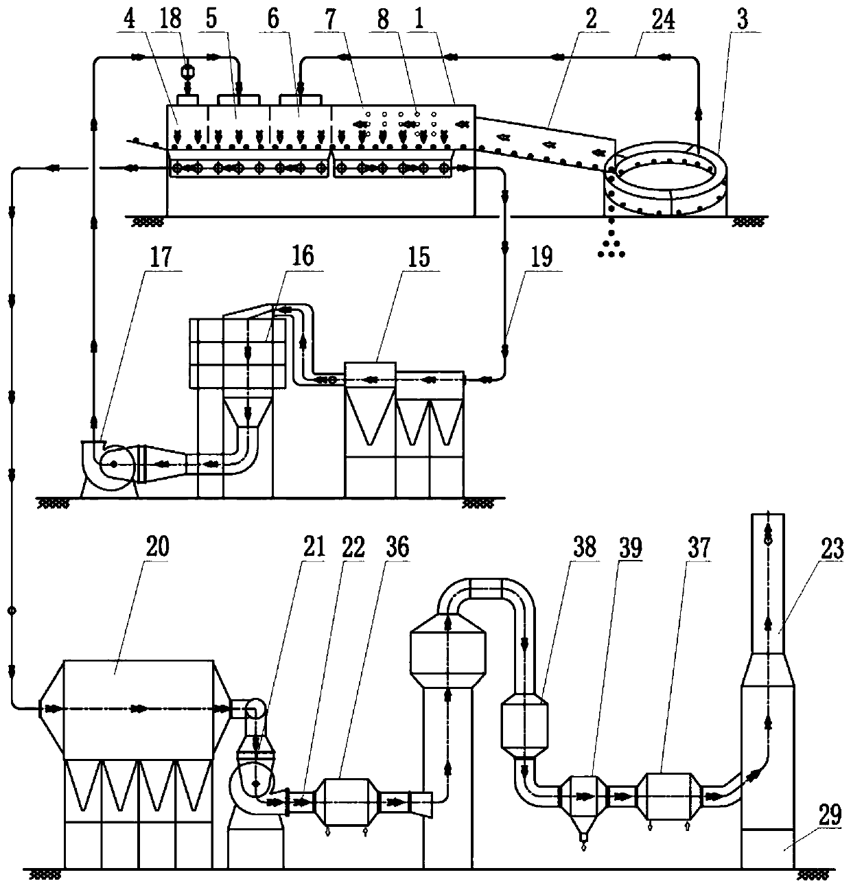
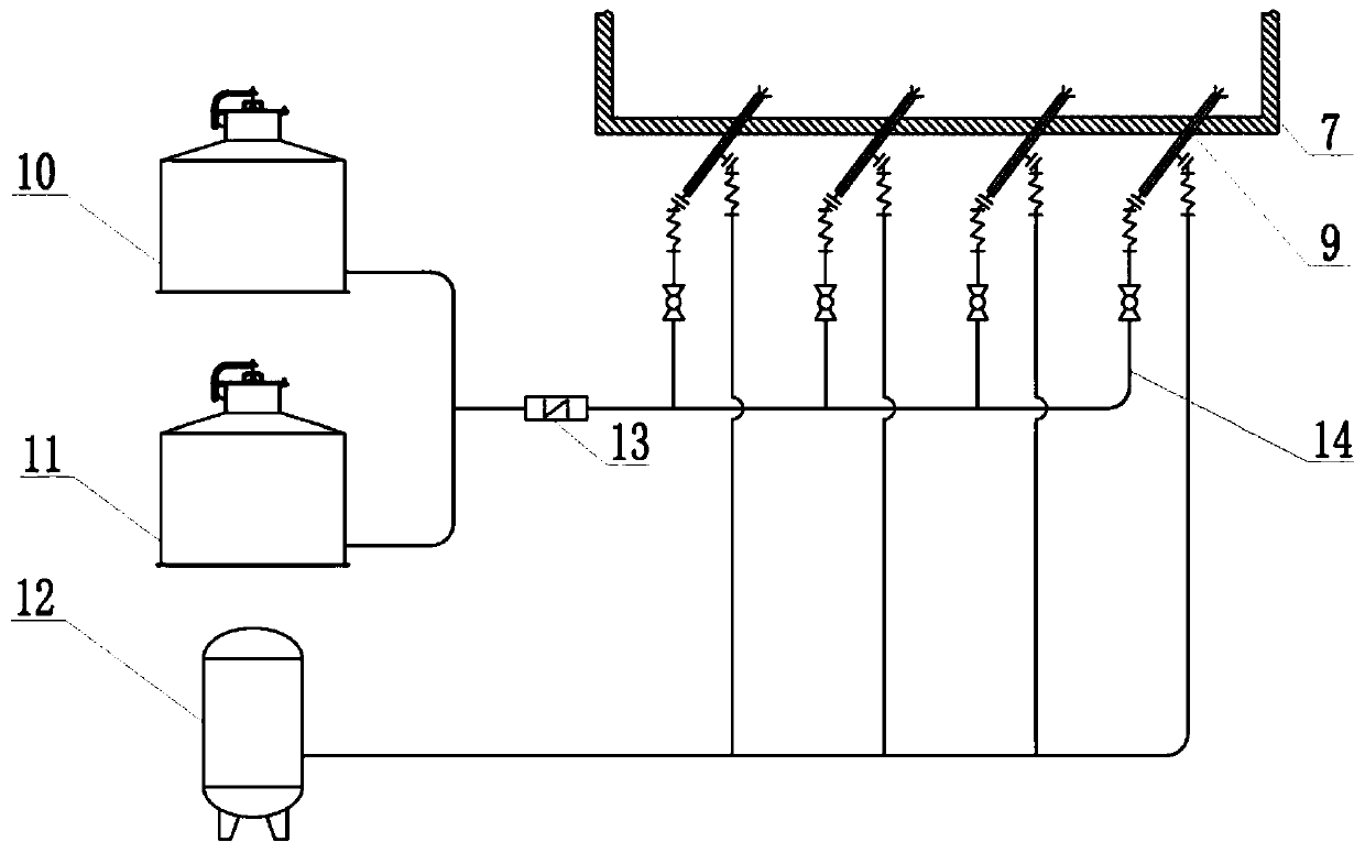
[0050] Reference figure 1 , The present invention provides a grate-rotary kiln pelletized ultra-low emission system, including the chain grate 1, rotary kiln 2 and ring cooler 3 connected in sequence, that is, the grate 1 is connected to the rotary kiln 2. The head, the ring cooler 3 is connected to the tail of the rotary kiln 2. The pellets are processed by the grate machine 1, the rotary kiln 2 and the ring cooler 3 before being discharged; among them, the grate machine 1 is away from the side of the rotary kiln 2 To the other side, it is divided into drying section 4, drying section 5, preheating section 6, preheating section 7; the flue gas outlet on the ring cooler 3 is connected to the flue gas of the grate machine 1 through the first flue path 24 On the gas inlet, this design is to recover the heat of the flue gas in the ring cooler 3; a first denitrification device 8 is provided in the second preheating section 7; the flue gas outlet at the bottom of the second preheatin...

Embodiment 2

[0080] This embodiment is an adjustment made on the basis of embodiment 1. This embodiment is adjusted for the desulfurization tower, and no other structure is changed.

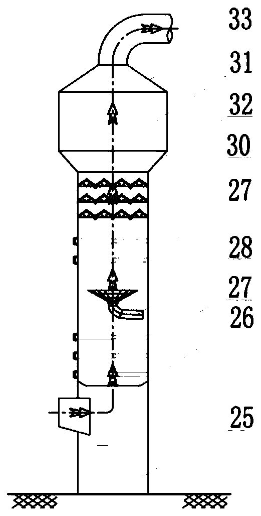
[0081] Specifically, refer to Figure 4 , In this embodiment, the desulfurization tower is a double tower and double circulation tower.

[0082] The double-tower double-circulation tower is divided into a first-stage tower 34 and a second-stage tower 35. In the first-stage tower 34, a first-stage slurry area 25, a liquid holding tray 26, and a first-stage spray layer 27 are arranged from bottom to top; and the second-stage tower 35 A secondary slurry area 29, a liquid holding plate 26, a spray layer 27, a mist removal device 30, and a third dust removal device 31 are sequentially arranged from bottom to top. The air outlet of the primary tower 34 is connected to the air inlet of the secondary tower 35, The primary tower 34 is a primary circulation system, and the secondary tower 35 is a secondary circulation syste...

Embodiment 3

[0087] This embodiment is an adjustment made on the basis of Embodiment 1 or 2. This embodiment is adjusted for the whitening device, and other structures are not changed.

[0088] Reference Figure 5 In this embodiment, the whitening device is a “one cooling and one heating” device, and “one cooling” is a heat extractor 36. The heat extractor 36 is arranged between the first fan 21 and the desulfurization device. After the heater 36, the temperature drops from 150°C to 110°C; “one temperature rise” is the temperature riser 37, which is located in front of the air inlet of the chimney 23. After the flue gas passes through the temperature riser 37, the temperature rises from 50°C to 80°C; The heat exchanger 36 and the temperature riser 37 exchange heat through a circulating heat medium water system. In this embodiment, when the atmospheric environment temperature is 5° C. and the humidity is 50%, there is no visible white smoke.


PUM


Abstract

The invention discloses a grate-rotary kiln pellet flue gas ultra-low emission system, including a grate, a rotary kiln and a ring cold machine which are sequentially connected, wherein the grate is divided into a first drying section, a second drying section, a first preheating section, and a second preheating section from the side away from the rotary kiln to the other side, and a flue gas outlet of the ring cold machine is connected to a flue gas inlet of the grate through a first flue gas passage; the second preheating section is internally provided with a first denitration device; a fluegas outlet at the bottom of the second preheating section is connected to flue gas inlets on the top of the first drying section and the top of the second drying section through a second flue gas passage, and a first dedusting device, a second denitration and a first fan are connected in series on the second flue gas passage; flue gas outlets on the bottom of the first drying section, the bottom of the second drying section, and the bottom of the first preheating section are connected onto a third flue gas passage; a second dedusting device, a second fan, a desulfurization device are connectedin series onthe third flue gas passage, and the tail end of the third flue gas passage is connected with a chimney.

Description

Technical field [0001] The invention relates to the technical field of grate machine-rotary kiln pellet flue gas treatment, in particular to a grate machine-rotary kiln pellet flue gas ultra-low emission system. Background technique [0002] In recent years, as my country's economic development has entered a new stage, society and government departments have increasingly demanded energy conservation and environmental protection. As a heavy industry, the steel industry has more and more stringent production flue gas emission indicators. Pellets are one of the commonly used charge for blast furnace ironmaking, and acid pellets or alkaline pellets with the corresponding sinter is the mainstream charge for blast furnace ironmaking in my country's iron and steel enterprises. The grate-rotary kiln method is the main method for the production of oxidized pellets in my country, and it occupies an important position in the preparation of blast furnace charge. [0003] With the increasing ...

Claims


Application Information

Patent Timeline
Patent Type & Authority Applications(China)
IPC IPC(8): B01D53/56B01D53/75B01D53/79B01D53/50B01D53/80B01D50/00B01D53/26
CPCB01D53/56B01D53/75B01D53/79B01D53/504B01D53/80B01D50/00B01D53/265B01D53/26B01D2251/2062B01D2251/404B01D2251/604B01D2258/0283B01D2258/025
Inventor 宗永生
Owner 江苏盐环实业有限公司
Why Eureka
Try Eureka