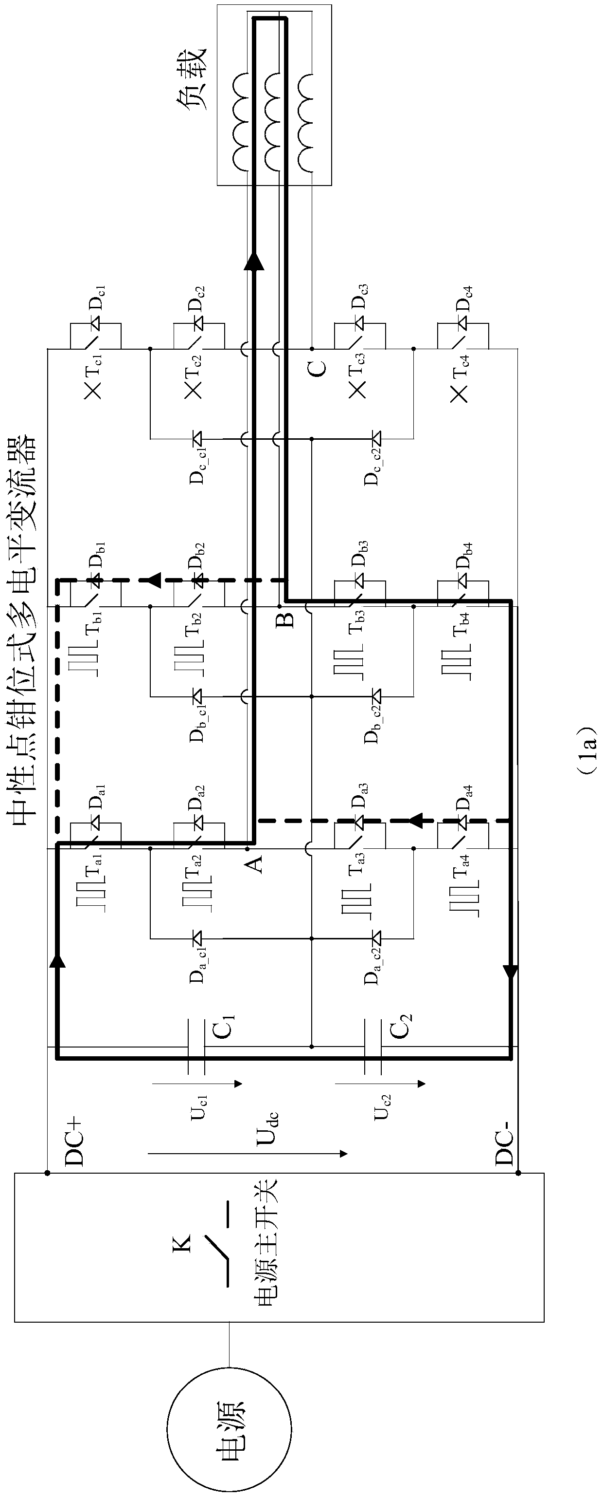
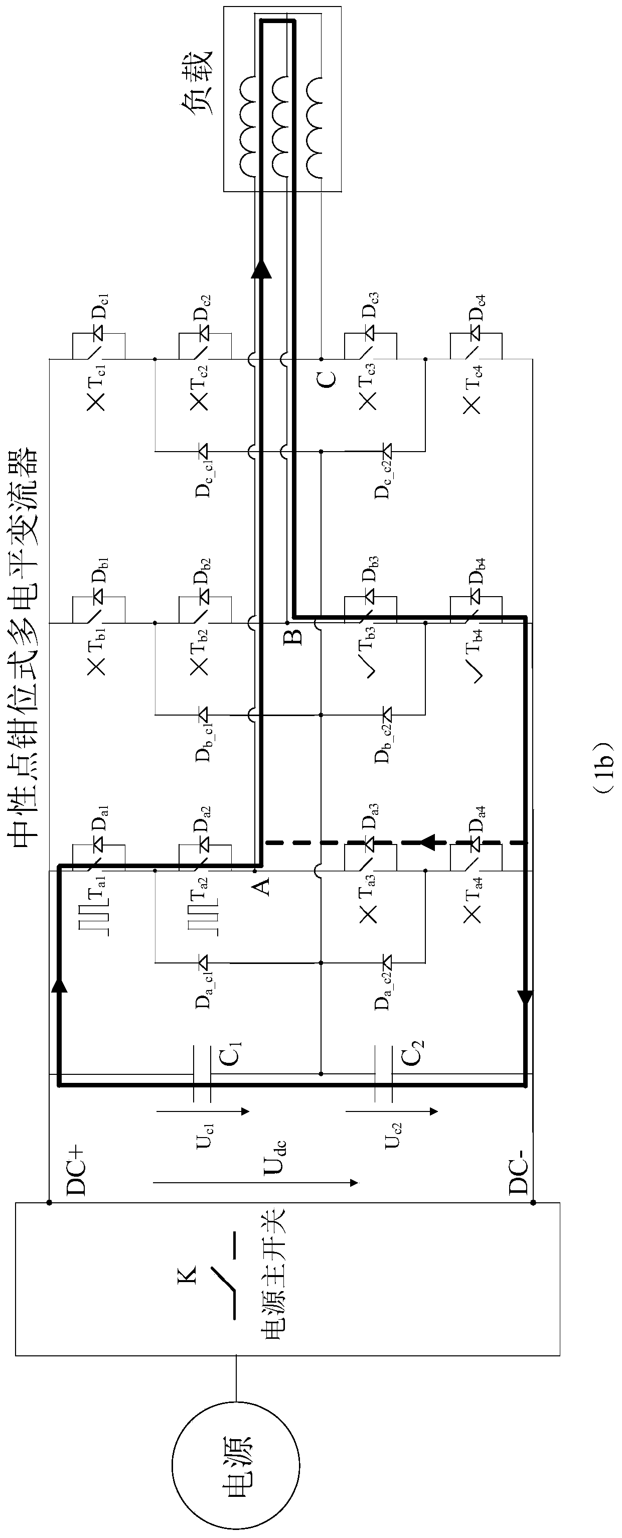
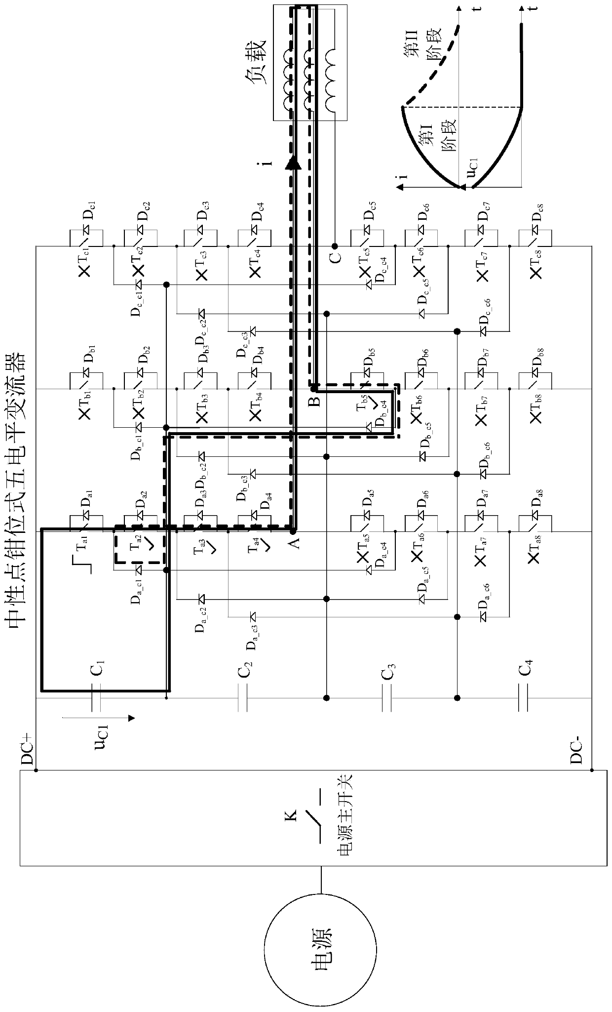
Neutral point clamping type multi-level converter direct current capacitor state detection method

A multi-level converter, neutral point clamp technology, applied in capacitance measurement, measurement of electrical variables, environmental/reliability testing, etc. system and other issues, so as to shorten the test time, consider comprehensively, and ensure the safety of the system.

Active Publication Date: 2019-08-30
TONGJI UNIV
View PDF6 Cites 5 Cited by
  • Summary
  • Abstract
  • Description
  • Claims
  • Application Information

AI Technical Summary

Problems solved by technology

Although the patent discloses the basic principle and main steps of the capacitance resonance detection method, the switching device control method in the capacitance control discharge and resonance detection stages proposed in the patent is only applicable to the two-level converter system and cannot be directly applied to neutral Point Clamp Multilevel Converter System

Method used


Image

  • Neutral point clamping type multi-level converter direct current capacitor state detection method
  • Neutral point clamping type multi-level converter direct current capacitor state detection method
  • Neutral point clamping type multi-level converter direct current capacitor state detection method

Examples


Embodiment 1

[0070] Embodiment 1: Simulation of DC capacitance detection of CHR2 three-level traction converter of Harmony EMU

[0071] Schematic diagram of CHR2 traction system of Harmony EMU Figure 5 As shown, the parameters are shown in Table 1.

[0072] Table 1 CHR2 Traction System Parameters

[0073]

[0074] The CRH2 traction system uses a pantograph to obtain power from the high-voltage power grid, and then supplies power to two traction converters after being stepped down by the traction transformer. Each traction converter uses a pulse rectifier to rectify single-phase alternating current to direct current, and then converts it to three-phase alternating current through an inverter, and drives four traction motors to provide power for the locomotive. In order to realize high-voltage and large-capacity power conversion and control, the pulse rectifier and inverter in the traction converter adopt a neutral-point clamped three-level converter structure.

[0075] The method pro...

Embodiment 2

[0076] Example 2: 380V / 10kVA neutral point clamped three-level converter DC capacitance detection experiment

[0077] In order to further verify the effectiveness and feasibility of the method of the present invention, a DC capacitance detection experiment was carried out in a 380V / 10kVA neutral point clamped three-level converter experimental system. Such as Figure 8 As shown, the experimental system uses an adjustable DC power supply to supply power to the three-level converter to drive the induction motor to rotate. The motor control adopts the constant current open-loop control mode, and the frequency and current of the converter can be set arbitrarily. The converter adopts Infineon 1.2kV / 30A neutral point clamped three-level IGBT power module (FS3L30R07W2H3F). The main controller of the converter adopts TI DSP28335, and samples the system voltage and current signals through the A / D sampling circuit. The DC capacitor pre-discharge and resonance test control algorithm i...


PUM


Abstract

The present invention relates to a neutral point clamping type multi-level converter direct current capacitor state detection method, comprising following steps: 1) direct current capacitor discharge:discharging the direct current capacitor of a neutral point clamp type multi-level converter, so that a voltage of the direct current capacitor drops to a safe voltage; 2) direct current capacitor resonance test: controlling a gate pulse of a switching device in any two phases of bridge arms in the neutral point clamping type multi-level converter to generate LC resonance between corresponding two phases of load inductances; 3) direct current capacitance detection: obtaining resonance current waveform data according to the detection and obtaining a magnitude of the direct current capacitor through a nonlinear regression algorithm. Compared with the prior art, the method has the advantages of simple testing, safe testing, fast discharging, high precision, comprehensive consideration, strong versatility and the like.

Description

technical field [0001] The invention relates to the technical field of detecting the state of a DC capacitor of a converter, in particular to a method for detecting the state of a DC capacitor of a neutral-point clamped multilevel converter. Background technique [0002] Since the 1990s, with the rapid development of fully controlled high-power power electronic devices represented by IGBT and IGCT, multilevel converters have been widely used in high-voltage and high-power applications. Among them, the neutral point clamped multilevel converter uses the clamp diode to effectively increase the number of levels, and can double the output voltage and power level of the converter without increasing the voltage stress of the device, so it is widely used in High-speed rail traction, wind power conversion, medium voltage frequency conversion and other important fields. As the core component in the neutral point clamped multilevel converter, DC capacitor has the functions of electri...

Claims


Application Information

Patent Timeline
Patent Type & Authority Applications(China)
IPC IPC(8): G01R31/00G01R27/26
CPCG01R27/2605G01R31/003G01R31/008
Inventor 向大为张少凡
Owner TONGJI UNIV
Why Eureka
Try Eureka