Micrometer precise holder motion control device and method

A motion control device and pan/tilt technology, applied in non-electric variable control, position/direction control, control/regulation systems, etc., can solve problems such as inaccurate ranging, not a constant value, and inability to meet precise target positioning. , to achieve the effect of improving repeated positioning accuracy and facilitating accurate aiming

Pending Publication Date: 2019-08-30
HUBEI JIUZHIYANG INFRARED SYST CO LTD
View PDF15 Cites 7 Cited by
  • Summary
  • Abstract
  • Description
  • Claims
  • Application Information

AI Technical Summary

Problems solved by technology

[0003] Most of the traditional security pan/tilts use a repeat positioning accuracy of only 0.1°. Basically, they are driven by stepping motors, and the step accuracy and repeat positioning accuracy are achieved through the indexing method. The motion accuracy of the gimbal cannot be further improved; and the use of a torque motor will make the price of the micrometer gimbal high. At the same time, the driving force is always balanced with the resistance after starting up, so that the power consumption is large, which is not suitable for high performance ratio. Required security industry
[0004] With the development of the security industry, the visible light cameras currently used in border security monitoring, fishery security monitoring and other fields use high-definition lenses with a focal length of 500mm or above, and thermal imaging cameras use lenses with a focal length of 100mm or above, and most of the working distances reach or far At 4km, if a gimbal with a repeat positioning accuracy of 0.1° is used, the positioning error for a family car or a fishing boat of about 5

Method used


Image

  • Micrometer precise holder motion control device and method
  • Micrometer precise holder motion control device and method
  • Micrometer precise holder motion control device and method

Examples


Embodiment Construction

[0037] The present invention will be described in further detail below in conjunction with the accompanying drawings and embodiments.

[0038] The first purpose of the present invention is to realize the repeatable positioning of the precision pan-tilt, which is conducive to fast aiming at the target, and the second purpose is to ensure that the first condition is met, each time the precise positioning is quickly completed, and the real-time positioning is ensured.

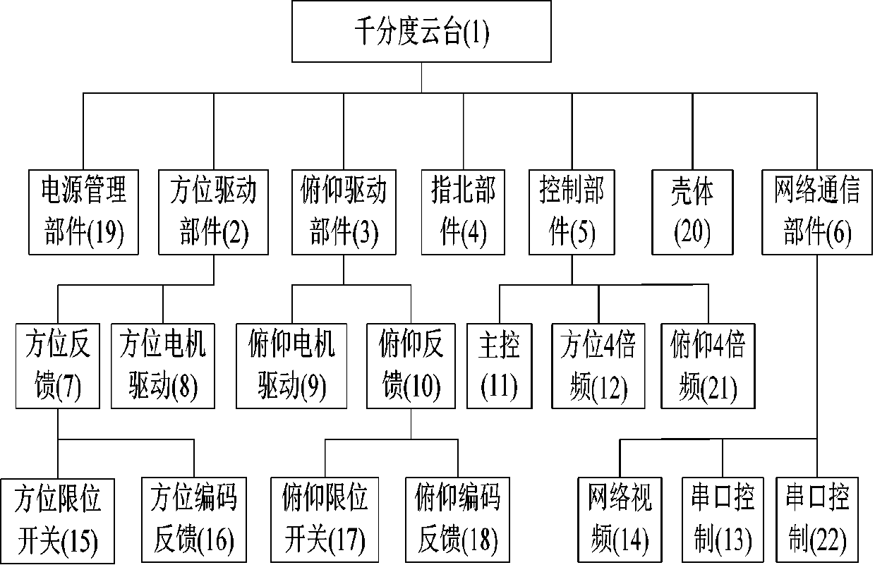
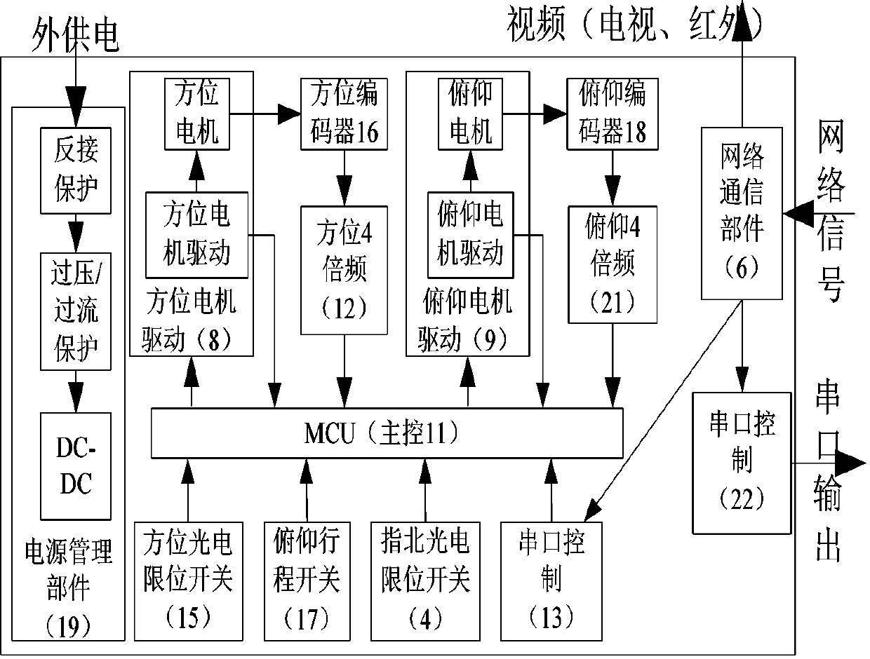
[0039] refer to figure 1 As shown, the micrometer pan / tilt 1 of the present invention is mainly composed of the following components: a power management component 19 , an azimuth drive component 2 , a pitch drive component 3 , a north component 4 , a control component 5 , a network communication component 6 and a housing 20 .

[0040] The azimuth driving part 2 is composed of an azimuth motor 27, an azimuth feedback module 7 and an azimuth motor drive module 8, and the azimuth feedback module 7 is composed of an a...


PUM


Abstract

The invention discloses a micrometer precise holder motion control device. The control device is composed of a shell, and an orientation driving component, a pitching driving part, a north part, a control part, a network communication part and a power supply management part arranged in the shell. The invention further discloses a control method of the control device. The control method comprises path planning, motion control and motion compensation. Through the path planning, a motion path is segmented, and for different path segments, different motion control algorithms are adopted: at the beginning, a relatively low starting speed is adopted for preventing the step-out of the motor, and by loading a driving force, a maximum speed is reached within the shortest time; at a high-speed motion stage, a uniform motion is performed at the maximum motion speed to guarantee the minimum motion time, so that the motion control time of a micrometer holder is optimized; and finally for a pitchingmotion, a lost motion position error of the holder caused by the influence of a load torque is eliminated through a compensation algorithm, so that the motion control precision of the holder is improved.

Description

technical field [0001] The invention belongs to the technical field of pan-tilt motion control, and in particular relates to a precise control device for the position of a thousand-division pan-tilt and a control method thereof. Background technique [0002] The PTZ is a common equipment in the security industry. With the development of the security industry, it is not only necessary to monitor the target in a timely manner, but also to accurately locate, measure and quickly track the target. [0003] Most of the traditional security pan / tilts use a repeat positioning accuracy of only 0.1°. Basically, they are driven by stepping motors, and the step accuracy and repeat positioning accuracy are achieved through the indexing method. The motion accuracy of the gimbal cannot be further improved; and the use of a torque motor will make the price of the micrometer gimbal high. At the same time, the driving force is always balanced with the resistance after starting up, so that the...

Claims


Application Information

Patent Timeline
IPC IPC(8): G05D3/12G05D3/14
CPCG05D3/12G05D3/1463
Inventor 雷志雄洪普郭晓东李振刘崇成
Owner HUBEI JIUZHIYANG INFRARED SYST CO LTD
Why Eureka
Try Eureka