Lead framework production system

A production system and lead frame technology, applied in the direction of electrical components, semiconductor/solid-state device manufacturing, circuits, etc., can solve the problems of high labor intensity, plating layer wear, low production efficiency, etc., to improve the automation process, reduce labor intensity, The effect of improving productivity

Active Publication Date: 2019-08-30
新恒汇电子股份有限公司
View PDF9 Cites 4 Cited by
  • Summary
  • Abstract
  • Description
  • Claims
  • Application Information

AI Technical Summary

Problems solved by technology

However, the labor intensity is high when done manually, and the surface of the lead frame is easily scratched during manual operation, resulting in product damage, and it is not conducive to the automatic process of lead frame generation
[0005] (2) During the transmission process of the frame semiconductor after the electroplating is completed, the electroplating layer is in contact with the surface of the conveyor belt, so it is easy to cause wear to the electroplating layer during the entire transmission process, which will have a great impact on the appearance and quality of the lead frame
[0006] (3) In the electroplating process, it is generally necessary to electroplate the electric frame one by one, so the production efficiency is low

Method used


Image

  • Lead framework production system
  • Lead framework production system
  • Lead framework production system

Examples


Embodiment 1

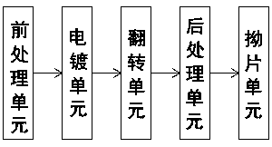
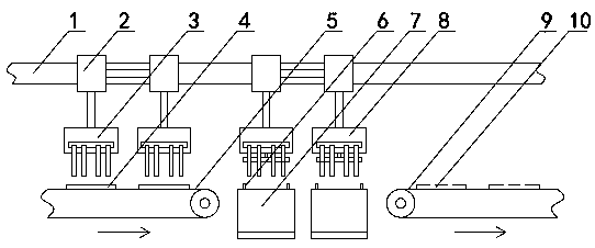
[0049] Such as figure 1 As shown, a lead frame production system includes a pre-processing unit, an electroplating unit, a flipping unit, a post-processing unit, and an angler unit arranged in sequence, combined with figure 2 , the frame 4 to be electroplated enters the electroplating unit for electroplating after going through the pretreatment procedures such as feeding, oil removal, acid neutralization, pre-copper plating, and anti-displacement in the pre-processing unit, and then the frame semi-finished product 10 is obtained after the electroplating is completed. 10 When it is exported from the electroplating unit, its electroplating layer 17 (see Figure 5 ) is in contact with the surface of the electroplating output conveyor belt 9, and the frame semi-finished product 10 is sent to the overturning unit through the electroplating output conveyor belt 9. After being overturned by the overturning unit, the electroplating layer 17 is no longer in contact with the subsequen...

Embodiment 2

[0089] In this embodiment, the angle sensor and the angle lever provided at the angle input conveyor belt 23 adopt the same technical scheme as the electroplating sensor 11 and the electroplating lever 12 at the five places on the electroplating input conveyor belt, which can realize two-piece For the shielding of the frame semi-finished products 10, two angle sliders 22 and the suction cups 24 at the bottom thereof are respectively provided with two, and the two frame semi-finished products 10 are transferred at the same time. 10 carry out the bending operation.


PUM


Abstract

The invention relates to a lead framework production system and belongs to the technical field of semiconductor production. The lead framework production system includes an electroplating unit, an overturning unit and a bending unit that are sequentially disposed. After a to-be-electroplated framework (4) is electroplated in the electroplating unit, a framework semi-finished product (10) is obtained and then enters the overturning unit, after the framework semi-finished product (10) is overturned by an overturning bin (13), front and back sides are reversed with each other, the framework semi-finished product (10) is placed on a surface of an overturning output conveyor (15) and conveyed by the overturning output conveyor (15) to a bending input conveyor(23) of the bending unit, separationof a framework single unit (35) and a framework frame (37) in the framework semi-finished product (10) is carried out in the bending unit, and the framework single unit (35) is transferred to a finished product zone (28). The lead framework production system is advantaged in that processes such as electroplating, overturning and bending in the lead framework production process are completed, automation of the lead framework is improved, and wear of the lead framework during transport is avoided.

Description

technical field [0001] A production system for a lead frame belongs to the technical field of semiconductor production. Background technique [0002] As the chip carrier of integrated circuits, the lead frame is a key structural part that realizes the electrical connection between the lead-out end of the chip's internal circuit and the outer lead by means of bonding materials (gold wire, aluminum wire, copper wire) to form an electrical circuit. It has reached the role of a bridge connected with external wires. The lead frame needs to be electroplated first in the production process. After the electroplating is completed, the frame semi-finished product is obtained. The structure of the frame semi-finished product is as follows Figure 15 As shown, it consists of a frame monomer 35 and a frame frame 37 surrounding the outer ring of the frame monomer 35. The frame monomer 35 and the frame frame 37 are connected by a number of connecting sections 36, and finally the frame semi...

Claims


Application Information

Patent Timeline
Patent Type & Authority Applications(China)
IPC IPC(8): H01L21/48H01L21/67
CPCH01L21/4821H01L21/4842H01L21/67196H01L21/6723H01L21/67236
Inventor 朱林朱春阳刘松源黄伟李昌文徐治陈迅马伟凯刘琪
Owner 新恒汇电子股份有限公司
Why Eureka
Try Eureka