
On-demand micro liquid drop generation method based on pneumatic and electrohydrodynamic hybrid driving

A technology of hybrid drive and production method, which is applied to the parts of color TV, parts of TV system, TV, etc., and can solve the problems of difficulty in realizing on-demand injection, increasing system cost, and inability to realize on-demand injection, etc.

Active Publication Date: 2019-09-03
BEIJING UNIV OF TECH
View PDF7 Cites 4 Cited by
  • Summary
  • Abstract
  • Description
  • Claims
  • Application Information

AI Technical Summary

Problems solved by technology

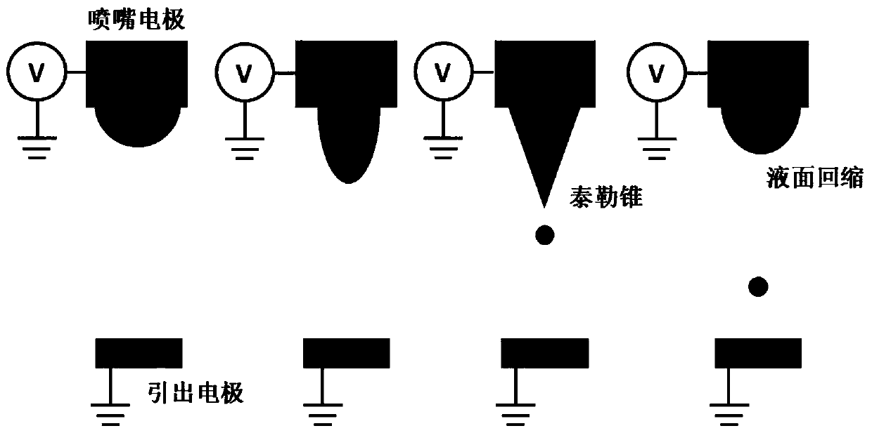
However, EHD micro-droplet ejection technology also needs to face many difficulties
Since the liquid generation is affected by the continuous electric field force and the flow rate of the liquid supply system, although the frequency of droplet generation is controlled by voltage, it is difficult to maintain stability, and it is impossible to achieve on-demand injection
Using a high-voltage pulse power supply can overcome the above-mentioned problem of unstable injection frequency to a certain extent, but on-demand injection is still difficult to achieve
At the same time, the price of high-voltage pulse power supply is much higher than that of high-voltage constant voltage power supply, which greatly increases the system cost

Method used


Image

  • On-demand micro liquid drop generation method based on pneumatic and electrohydrodynamic hybrid driving
  • On-demand micro liquid drop generation method based on pneumatic and electrohydrodynamic hybrid driving
  • On-demand micro liquid drop generation method based on pneumatic and electrohydrodynamic hybrid driving

Examples


Embodiment Construction

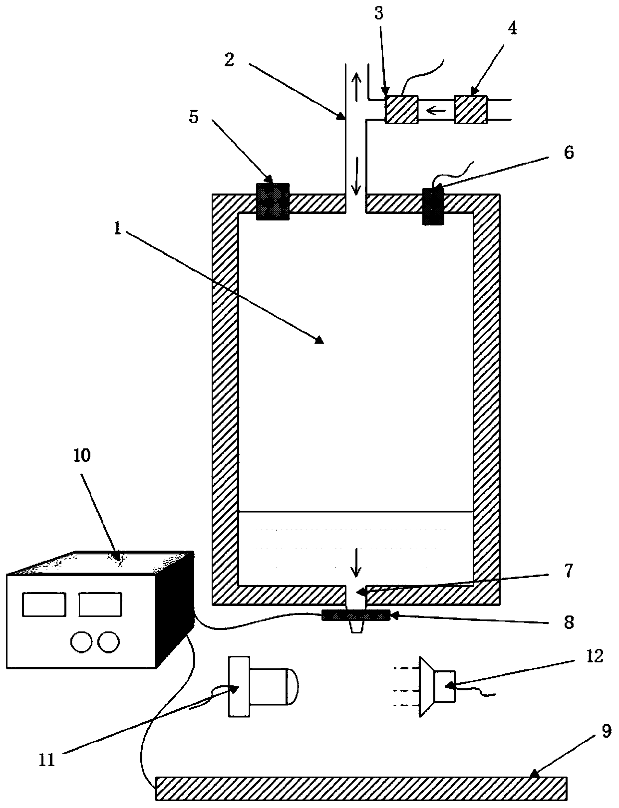
[0013] The device consists of liquid storage chamber 1, air inlet and outlet pipes 2, high-speed solenoid valve 3, pressure regulating valve 4, liquid filling hole 5, air pressure sensor 6, nozzle 7, electrode 8, lead-out electrode 9, high voltage stabilized power supply 10, industrial camera 11 and LED lamp 12 forms. The liquid storage chamber 1 is used to store liquid, the high-speed solenoid valve 3 is used to control the opening and closing of high-pressure gas, the pressure regulating valve 4 adjusts the intake pressure, and the air pressure sensor 6 monitors the pressure in the liquid storage chamber 1. The high voltage stabilized power supply 10 provides high voltage for the EHD system. The LED lamp 12 provides a light source for the industrial camera 11 . The liquid filling hole 5 is used to inject liquid into the liquid storage cavity 1 .

[0014] The specific implementation steps of generating micro-droplets and adjusting the size are as follows:

[0015] S1: Use ...


PUM


Abstract

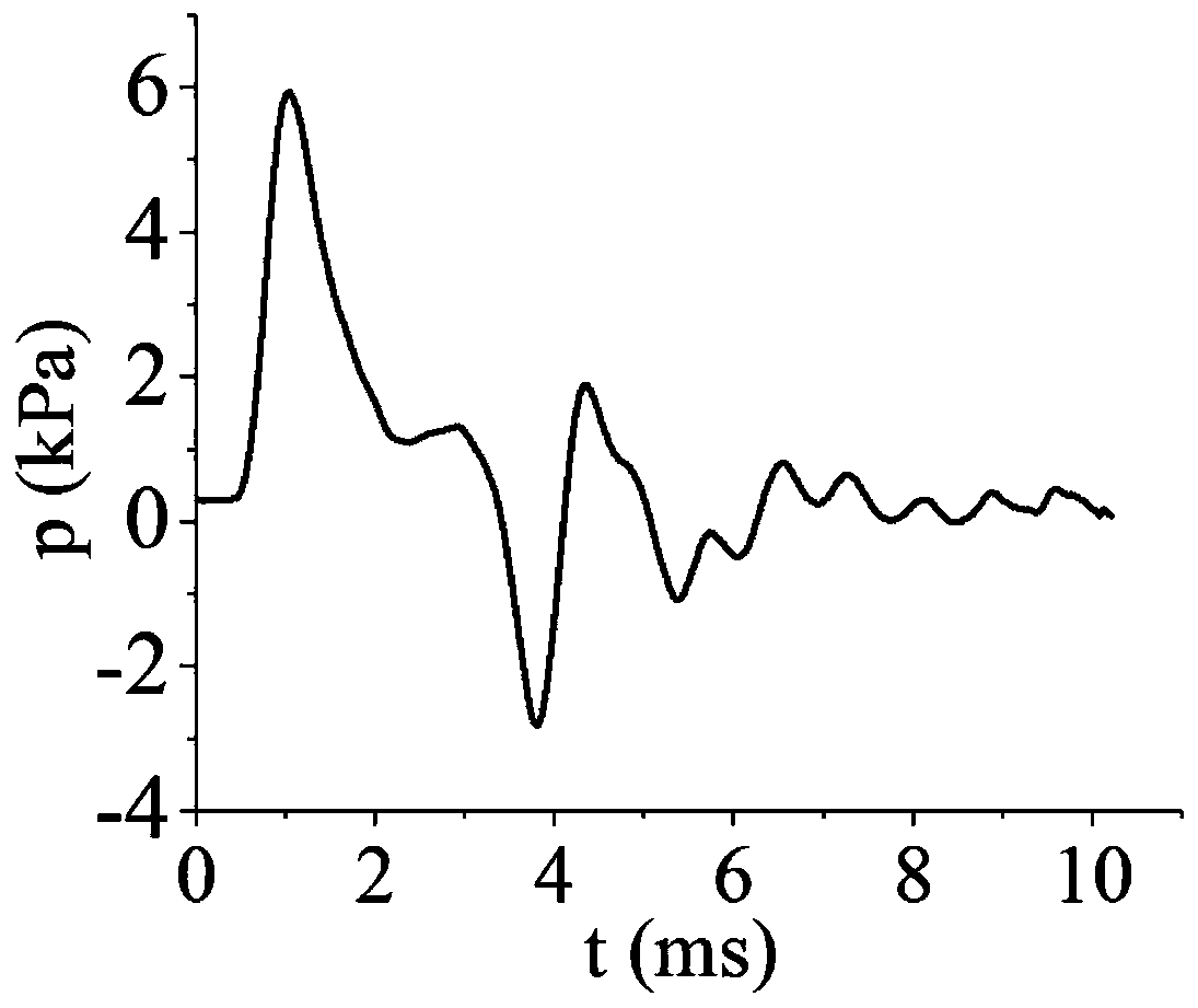
The invention discloses an on-demand micro liquid drop generation method based on pneumatic and electrohydrodynamic hybrid driving. The device for realizing the method is supplied by a high-pressure gas source, a pressure regulating valve is used for controlling the air pressure at the front end of a high-speed electromagnetic valve, and a single-chip microcomputer controls the opening time of thehigh-speed electromagnetic valve. After the high-pressure gas enters a liquid storage cavity, helmholtz oscillation is generated, and the high-pressure gas is stable after being attenuated by severalperiods. An industrial camera and an LED lamp are used for monitoring the production process of the micro liquid drops and adjusting the system in an auxiliary mode. The high-speed electromagnetic valve and the pressure regulating valve are reasonably adjusted according to the air pressure waveform detected by an air pressure sensor. The air pressure waveform is controlled by adjusting the high-speed electromagnetic valve and the pressure regulating valve, the volume and shape of the micro liquids extruded from a nozzle can be adjusted, so that the size of the micro liquid drops is regulated.Compared with a high-voltage pulse power supply micro liquid drop generating device, the cost is greatly reduced.

Description

technical field [0001] The invention relates to a micro-droplet generation device driven by a mixture of pneumatic and electrohydrodynamics, and realizes the control technology of generating micro-droplets on demand and adjusting its size by adjusting the opening time, air pressure and voltage level of the electromagnetic valve in the device , mainly used in the application of micro-liquid samples, and can be used in printing electronics, drug development, biomedical material printing and other fields. Background technique [0002] As conventional inkjet printing technologies, including piezo-actuated jetting and thermal bubble-actuated jetting, have expanded to other reference areas, more unconventional inkjet printing technologies have also made great progress. These unconventional injection methods mainly include pneumatically driven injection, electrohydrodynamic (EHD) injection, etc. They are used in a wide range of fields including biomedical printing. Among them, th...

Claims


Application Information

Patent Timeline
IPC IPC(8): B41J2/04B41J2/06B41J29/00H04N5/225
CPCB41J2/04B41J2/06B41J29/00H04N23/58
Inventor 王志海王一玮包伟捷王飞张海义
Owner BEIJING UNIV OF TECH
Learn More