Integrated substrate gap waveguide feed slot coupling metasurface antenna

An integrated substrate and waveguide feeding technology, applied in antennas, antenna couplings, antenna components, etc., can solve problems such as leakage, narrow bandwidth of millimeter-wave antennas, and low gain, and achieve the goal of increasing gain, increasing bandwidth, and reducing thickness Effect

Pending Publication Date: 2019-09-03
YUNNAN UNIV
View PDF4 Cites 16 Cited by
  • Summary
  • Abstract
  • Description
  • Claims
  • Application Information

AI Technical Summary

Problems solved by technology

[0005] The purpose of the present invention is to: aim at the above existing problems, provide an integrated substrate gap waveguide feeding slot coupling metasurface antenna, which solves the problems of narrow bandwidth, low gain and serious leakage of existing millimeter wave antennas, and can Application of the invention to radio frequency, microwave and millimeter wave frequency bands

Method used


Image

  • Integrated substrate gap waveguide feed slot coupling metasurface antenna
  • Integrated substrate gap waveguide feed slot coupling metasurface antenna
  • Integrated substrate gap waveguide feed slot coupling metasurface antenna

Examples


Embodiment 1

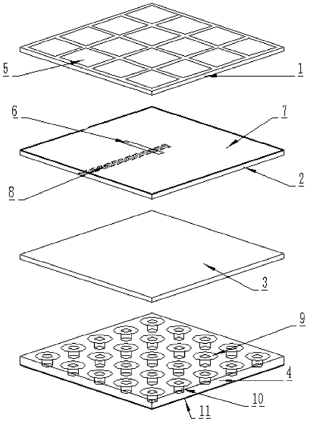
[0045] Such as figure 1 As shown, the present invention includes a first medium plate 1, a second medium plate 2, a third medium plate 3, and a fourth medium plate 4; the first medium plate 1, the second medium plate 2, the third medium plate 3, The fourth dielectric board 4 is pressed together to form a whole. ISGW substrate integrated gap waveguide.

[0046] The upper surface of the first dielectric board 1 has periodically arranged corner-cut patches 5 as a radiation structure, and the upper surface of the second dielectric board 2 has a first copper clad layer 7 as an antenna ground.

[0047] The integrated substrate gap waveguide structure is composed of a second dielectric board 2, a third dielectric board 3 and a fourth dielectric board 4; the upper surface of the second dielectric board 2 has a first copper clad layer 7, and the lower surface of the second dielectric board 2 is printed with With a feeder 8; a rectangular slit 6 is etched on the first copper clad laye...

Embodiment 2

[0058] Such as Figure 4 As shown, on the basis of Embodiment 1, the square patches 5 are replaced with corner-cut patches 12 .

[0059] Among them, the first dielectric plate 1, the second dielectric plate 2, and the third dielectric plate 3 are made of materials with a dielectric constant of 2.2 and a loss tangent of 0.0009; the fourth dielectric plate 4 is made of a material with a dielectric constant of 4.4 and a loss tangent of 0.0009. Made from a material with a tangent of 0.02. The overall size of the antenna is 12mm*12mm*1.362mm.

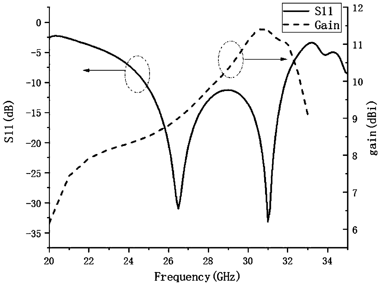
[0060] attached Figure 5 The shown return loss, gain and axial ratio simulation results show that a kind of ISGW feeding slot coupling metasurface circularly polarized antenna of the present invention has a center frequency of 28.08GHz, a -10dB impedance bandwidth of 25.34GHz-30.81GHz, and an absolute bandwidth of 5.47GHz , the relative bandwidth is 19.5%, the 3dB axial ratio bandwidth is 28.15GHz-32.28GHz, the absolute bandwidth is 4.13...

Embodiment 3

[0063] Such as Figure 7 As shown, the present invention includes a first dielectric board 1, a second dielectric board 2, and a fourth dielectric board 4; the first dielectric board 1, the second dielectric board 2, and the fourth dielectric board 4 are pressed together to form a overall.

[0064] The upper surface of the first dielectric board 1 has periodically arranged square patches 5 or corner-cut patches 12 as a radiation structure, and the upper surface of the second dielectric board 2 has a first copper clad layer 7 as an antenna ground.

[0065] The integrated substrate gap waveguide structure is composed of a second dielectric board 2 and a fourth dielectric board 4; the upper surface of the second dielectric board 2 has a first copper clad layer 7, and the lower surface of the second dielectric board 2 is printed with a microstrip feeder 8; the first Rectangular slits 6 are etched on the copper clad layer 7 ; metal via holes 10 arranged periodically are opened on ...


PUM


Abstract

The invention discloses an integrated substrate slot waveguide feed slot coupling metasurface antenna. The integrated substrate slot waveguide feed slot coupling metasurface antenna comprises an antenna radiation structure and an integrated substrate slot waveguide structure, wherein the antenna radiation structure and the integrated substrate slot waveguide structure are sequentially arranged andoverlapped from top to bottom; the integrated substrate slot waveguide structure includes an electromagnetic bandgap structure for shielding electromagnetic radiation energy and a feed structure fortransmitting energy to the antenna radiation structure. The feed structure comprises a second dielectric plate, the upper surface of the second dielectric plate is coated with a first copper-coated layer, and a slot is etched in the middle portion of the first copper-coated layer; and the lower surface of the second dielectric plate is provided with a microstrip feeder. The integrated substrate slot waveguide feed slot coupling metasurface antenna has the characteristics of a low profile, a wide bandwidth, a high gain, easiness in processing and the like, and can be used as a 5G millimeter wave antenna.

Description

technical field [0001] The invention relates to a wireless communication millimeter wave antenna, in particular to an integrated substrate gap waveguide feeding slot coupling metasurface antenna. Background technique [0002] With the development of communication systems, people's requirements for the frequency of devices in the microwave and millimeter wave bands continue to increase. When the traditional microstrip line structure is applied to higher frequencies, greater loss and leakage will occur. [0003] The integrated substrate gap waveguide can better solve the above problems. The structure is based on multi-layer PCB technology, and the microstrip line is encapsulated in the electromagnetic bandgap structure to improve the shielding of the feed network. In recent years, metasurface structures have been used in antenna design, which can improve the performance of antennas in various aspects, such as expanding bandwidth, increasing gain, improving pattern, etc., and ...

Claims


Application Information

Patent Timeline
Patent Type & Authority Applications(China)
IPC IPC(8): H01Q1/38H01Q1/48H01Q1/50H01Q1/52H01Q15/00
CPCH01Q1/38H01Q1/48H01Q1/50H01Q1/526H01Q15/0086
Inventor 申东娅周养浩袁洪
Owner YUNNAN UNIV
Why Eureka
Try Eureka