
A DC converter and energy storage system

A converter, direct current technology, applied in systems that store electrical energy, convert direct current power input to direct current power output, current collectors, etc., can solve problems such as affecting the conversion efficiency of converters, achieve stable output voltage, avoid excitation current, voltage Wide gain range effect

Active Publication Date: 2021-01-08
NORTH CHINA UNIVERSITY OF TECHNOLOGY
View PDF0 Cites 0 Cited by
  • Summary
  • Abstract
  • Description
  • Claims
  • Application Information

AI Technical Summary

Problems solved by technology

However, the conventional CLLC resonant converter suffers from the conduction loss caused by the high magnetizing current provided by the low-voltage side, which affects the conversion efficiency of the converter.

Method used


Image

  • A DC converter and energy storage system
  • A DC converter and energy storage system
  • A DC converter and energy storage system

Examples


Embodiment Construction

[0040] In order to make the objects, technical solutions and advantages of the present invention more apparent, exemplary embodiments according to the present invention will be described in detail below with reference to the accompanying drawings. Apparently, the described embodiments are only some embodiments of the present invention, rather than all embodiments of the present invention, and it should be understood that the present invention is not limited by the exemplary embodiments described here.

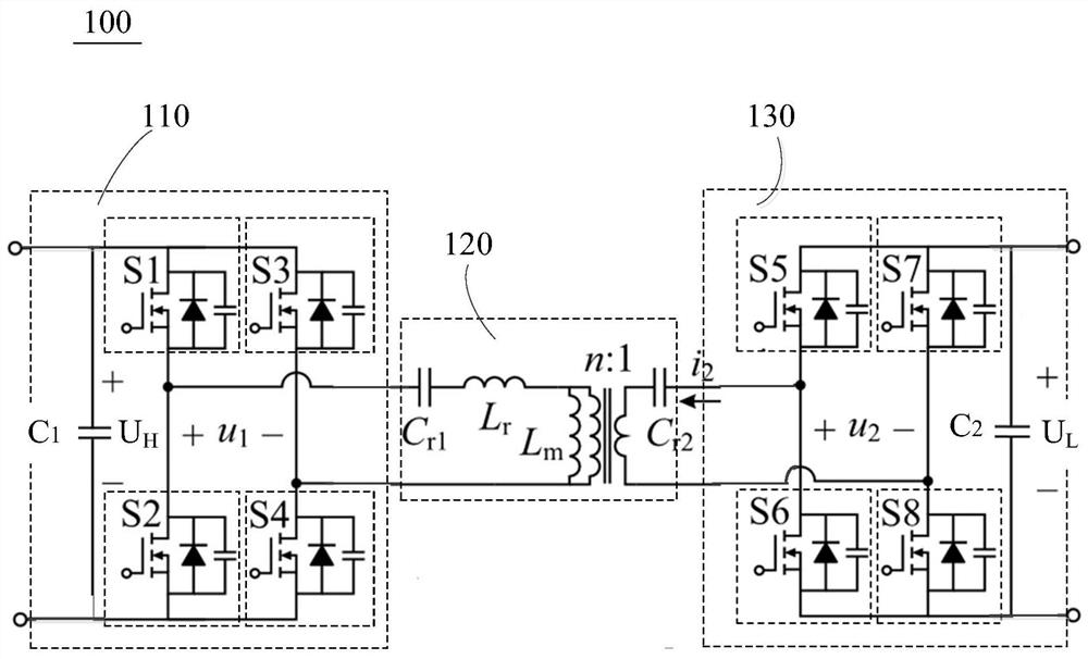
[0041] In order to solve the conduction loss problem of the CLLC resonant converter caused by the high magnetizing current provided by the low-voltage side, an embodiment of the present invention provides a direct current converter. The following will refer to figure 1 A DC converter according to one embodiment of the present invention will be described in detail. figure 1 A schematic circuit diagram of a DC converter 100 according to an embodiment of the present invention is ...


PUM


Abstract

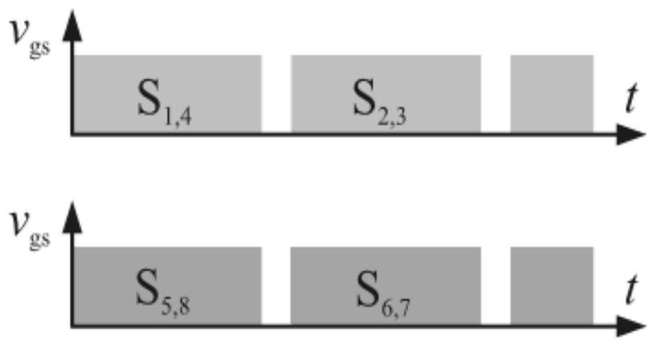
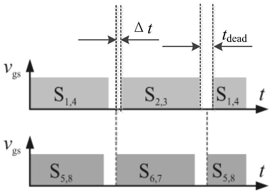
The invention provides a direct current converter and an energy storage system. The converter includes a high-side H-bridge, a CLLC resonant cavity, and a low-side H-bridge. The duty ratio of the control signal of the switch tube in the high-voltage side H-bridge and the control signal of the switch tube in the low-voltage side H-bridge is the same, and the control signal of the switch tube in the low-voltage side H-bridge is the same as that of the switch tube in the high-voltage side H-bridge. There is a phase shift time difference Δt between the control signals, so that the control signal of the switch tube in the low-voltage side H-bridge is ahead of the control signal of the switch tube in the high-voltage side H-bridge, wherein the phase-shift time difference Δt does not exceed the dead time t dead . By improving the synchronous rectification mechanism, the converter of the present invention effectively avoids the excitation current from the low-voltage side, reduces the conduction loss, thereby improving the conversion efficiency of the converter; The output voltage is more stable.

Description

technical field [0001] The invention relates to the field of power conversion, and more specifically relates to a DC converter and an energy storage system. Background technique [0002] Power to Gas (P2G) is an emerging large-scale energy storage solution, which is realized by using excess power from renewable energy power stations to produce hydrogen or synthetic natural gas, and consume natural gas for power generation during periods of high demand . One of the reliable implementation schemes is to use solid oxide cells (Solid Oxide Cell, SOC for short) to exchange energy with the grid through a bidirectional converter, thereby storing excess power. The bidirectional converter needs to be able to support the DC-DC conversion requirements of high voltage ratio and wide output range. The cascade design can be used to meet the DC-DC conversion requirements of high voltage ratio and wide output range, but the cascade design requires more components and multi-level control, ...

Claims


Application Information

Patent Timeline
Patent Type & Authority Patents(China)
IPC IPC(8): H02M3/335H02J15/00H02J7/00
CPCH02M3/33584H02M3/33592H02J15/00H02J7/0068H02M1/0054H02J2207/20Y02B70/10
Inventor 梅杨
Owner NORTH CHINA UNIVERSITY OF TECHNOLOGY
Learn More