
Method, device and system for remotely measuring Flicker scintillation value of liquid crystal module

A liquid crystal module and flicker value technology, applied in the direction of instruments, static indicators, etc., can solve the problems of limited number of collection frames, low detection efficiency of production line, and large number of collected frames, etc., to achieve rapid detection and improve detection efficiency and the effect of production yield

Active Publication Date: 2019-09-06
WUHAN JINGLI ELECTRONICS TECH +1
View PDF8 Cites 8 Cited by
  • Summary
  • Abstract
  • Description
  • Claims
  • Application Information

AI Technical Summary

Problems solved by technology

These methods need to scan the LCD module with a measuring head such as an optical probe to measure its brightness during the detection process. The optical probe should be as close to or close to the screen as possible to reduce external interference, and only the panel covered by the measuring head can be detected each time. range, it is difficult to meet the requirements of long-distance detection of flicker values ​​of large-area display panels in the production line, and the detection takes a long time; on the other hand, this type of method can only ensure accurate data when the measurement distance is not greater than 100mm, and cannot be used for LCD Module Flicker flicker value for more accurate measurement at a longer distance
[0004] The method and device (CN109147709A) of a kind of multi-point adjustment liquid crystal panel Flicker that the applicant applied for earlier adopts the signal of brightness and frame rate to carry out Fourier transformation to obtain Flicker value; Limitation, when it is actually applied to Flicker value detection, it needs to collect a large number of frames, and the efficiency of production line detection is not high

Method used


Image

  • Method, device and system for remotely measuring Flicker scintillation value of liquid crystal module
  • Method, device and system for remotely measuring Flicker scintillation value of liquid crystal module
  • Method, device and system for remotely measuring Flicker scintillation value of liquid crystal module

Examples


Embodiment Construction

[0042] In order to make the object, technical solution and advantages of the present invention more clear, the present invention will be further described in detail below in conjunction with the accompanying drawings and embodiments. It should be understood that the specific embodiments described here are only used to explain the present invention, not to limit the present invention. In addition, the technical features involved in the various embodiments of the present invention described below can be combined with each other as long as they do not constitute a conflict with each other.

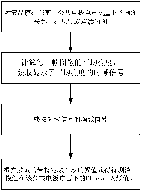
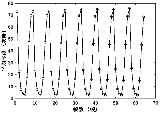
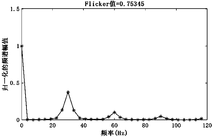
[0043] The method, device and system for measuring the Flicker flicker value of a liquid crystal module at a long distance provided by the present invention are at a certain common electrode voltage V com Use image acquisition equipment such as cameras and video cameras to continuously take pictures of the display screen or shoot video files, and calculate the average brightness of each frame...


PUM


Abstract

The invention belongs to the technical field of display panel detection, and discloses a method, a device and a system for remotely measuring a Flicker scintillation value of a liquid crystal module.The method includes: carrying out continuous image capturing on a display image of the liquid crystal module under a certain common electrode voltage; obtaining the average brightness of the image frames, obtaining the change relation of the brightness with the number of collected frames or time, i.e., the time domain signal of the brightness, obtaining the spectrogram of the brightness through the time domain signal, and obtaining the Flicker scintillation value of the liquid crystal module to be detected under the common electrode voltage through the amplitude of the specific frequency wave.The device comprises equipment for continuously capturing images of a liquid crystal module under a certain common electrode voltage, A calculation processing module used for calculating the averagebrightness to obtain a time domain signal of the brightness, A Fourier transform module used for carrying out fast Fourier transform on the time domain signal of the brightness, and A Flicker scintillation value calculation module used for calculating a Flicker scintillation value. according to the method and the system, the Flicker scintillation value of the display screen can be remotely measured, and the method and the system are used for monitoring the flicker degree of the liquid crystal display screen in real time in a panel production line.

Description

technical field [0001] The invention belongs to the technical field of liquid crystal display panel detection, and more specifically relates to a method, device and system for remotely measuring the Flicker flicker value of a liquid crystal module. Background technique [0002] Thin film transistor liquid crystal display (TFT-LCD) occupies a pivotal position in the display industry. TFT-LCD controls the deflection of liquid crystal molecules by applying different voltages to the pixel electrodes and forming an electric field with the common electrode, so as to achieve the purpose of light transmission and light shielding. The voltage difference between the pixel electrode and the common electrode determines the display gray scale. When the TFT-LCD is working, the polarity of the pixel voltage changes periodically to avoid DC residual and DC blocking effects. Every time the LCD screen is refreshed, the polarity of the pixel voltage changes once. If the Common electrode volt...

Claims


Application Information

Patent Timeline
Patent Type & Authority Applications(China)
IPC IPC(8): G09G3/00G09G3/36
CPCG09G3/006G09G3/36
Inventor 冯晓帆刘璐宁郑增强张胜森杨攀
Owner WUHAN JINGLI ELECTRONICS TECH
Learn More