Eureka AIR delivers breakthrough ideas for toughest innovation challenges, trusted by R&D personnel around the world.

Portable spherical direct methanol fuel cell

A methanol fuel cell, portable technology, applied in the direction of fuel cells, fuel cell parts, circuits, etc., can solve the problems of cumbersome production methods, reduce the performance of membrane electrodes, and difficult assembly, so as to save time and economic costs and improve carbon dioxide Manage and reduce the effects of toxic by-products

Pending Publication Date: 2019-09-06
SOUTH CHINA UNIV OF TECH
View PDF0 Cites 3 Cited by
  • Summary
  • Abstract
  • Description
  • Claims
  • Application Information

AI Technical Summary

Problems solved by technology

[0003] Although the traditional planar DMFC has a simple structure and is more convenient to manufacture, it also has many shortcomings such as bulky overall structure of the battery, low volume-to-power ratio and mass-to-power ratio, poor product management performance, high cost of bipolar plates, and difficult sealing of battery components.
[0004] For the existing tubular DMFC, the production method is cumbersome, the assembly is relatively difficult, the mass is heavy, and the flow field structure is single, which cannot meet the needs of the battery for good product management. The membrane electrode is prone to cracks during the high-bending process and the catalyst layer falls off. The performance of the membrane electrode is greatly reduced

Method used

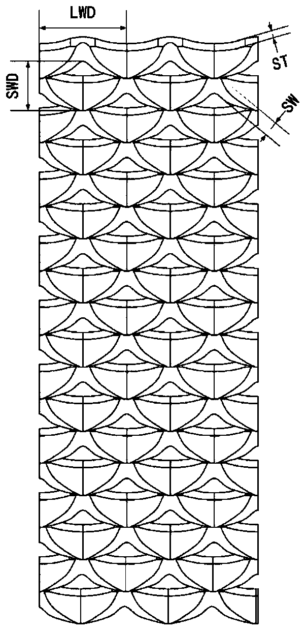

Image

  • Portable spherical direct methanol fuel cell
  • Portable spherical direct methanol fuel cell
  • Portable spherical direct methanol fuel cell

Examples


Embodiment Construction

[0034] In order to further understand the present invention, the present invention will be further described below in conjunction with the accompanying drawings. However, it should be noted that the protection scope of the present invention is not limited to the scope described in the following examples.

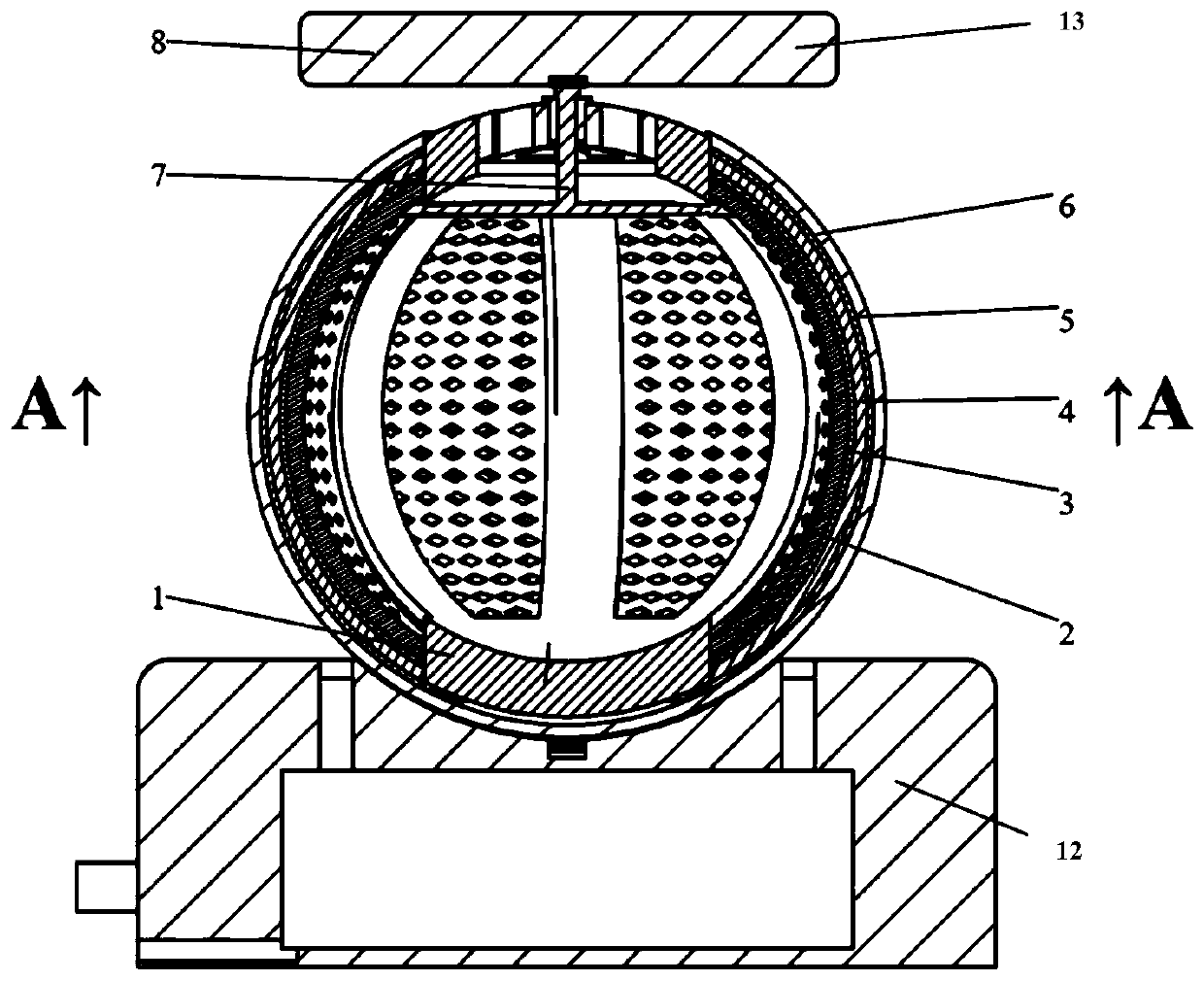
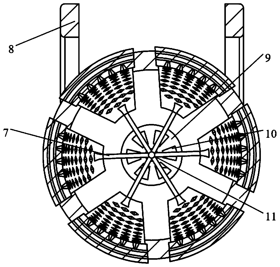
[0035] Such as figure 1 and figure 2 As shown, a portable spherical direct methanol fuel cell includes a base 8, a grid hole casing 1 arranged on the base 8, a plurality of anode collector plates 2, a catalytic layer 3, an alcohol barrier layer 4, a membrane electrode 5, Cathode current collector 6. The grid hole housing 1 is spherical in shape with a closed lower end, an open upper end and an end cover 9. The circumferential wall of the grid hole housing 1 is evenly provided with a number of arc-shaped grids parallel to the meridian. The left and right sides of the arc-shaped grid are provided with arc-shaped slots for limiting the anode collector plate 2 . The grid ho...


PUM


Abstract

The invention discloses a portable spherical direct methanol fuel cell. The portable spherical direct methanol fuel cell comprises a substrate, a grid hole shell, a plurality of positive current collecting plates, a catalyst layer, a methanol resistance layer, membrane electrodes, a negative current collector and external guide lines, wherein the grid hole shell is in the shape of a ball or an ellipsoid, the upper end of the grid hole shell is closed, an opening is formed in the upper end of the grid hole shell, and an end cover is arranged at the upper end of the grid hole shell; a pluralityof arc-like grids parallel to longitude lines are uniformly arranged on the peripheral wall of the grid hole shell along the circumferential direction; the end cover is provided with the external guide lines for connecting each positive current collecting plate; the positive current collecting plates, the catalyst layer, the methanol resistance layer and the membrane electrodes cling to the arc-like grids of the grid hole shell from inside to outside in sequence consistently; the membrane electrodes and the peripheral surface of the grid hole shell are coplanar; and the membrane electrodes arefastened to the peripheral surface of the grid hole shell in an arc-like mode and are in tight contact with the outer surfaces of the corresponding membrane electrodes. Through spherical design, theoutput performance and volume to power ratio of the call are improved, and simultaneously, the cell is convenient for subsequent maintenance while stack can be integrated to realize high-power output.

Description

technical field [0001] The invention relates to the technical field of direct methanol fuel cells, in particular to a portable spherical direct methanol fuel cell. Background technique [0002] The electric energy generated by the fuel cell is directly converted from the chemical energy of the raw material itself, and has the advantages of high energy density, low environmental pollution, and the abundance of raw materials, and has received more and more attention. . Among them, compared with the proton exchange membrane fuel cell hydrogen fuel cell, which has many factors such as high production cost of hydrogen raw materials, dangerous storage and transportation, and harsh use conditions, the direct methanol fuel cell (DMFC for short) belonging to the same category is more Methanol is the raw material for the anode. It has good application prospects due to its low working temperature (generally working at room temperature), high theoretical specific energy, convenient por...

Claims


Application Information

Patent Timeline
Patent Type & Authority Applications(China)
IPC IPC(8): H01M8/1011H01M8/0202
CPCH01M8/1011H01M8/0202Y02E60/50
Inventor 袁伟郑天翔徐晓林苏晓晴李嘉毅李锦广庄梓译王阳妹卢彪武
Owner SOUTH CHINA UNIV OF TECH
Why Eureka
Eureka Blog
Learn More