Multi-output mode conversion control circuit of switching power supply

An output mode, conversion control technology, applied in output power conversion devices, control/regulation systems, conversion of DC power input to DC power output, etc. To avoid problems such as mechanical wear and tear of the device, to achieve the effect of improving flexibility and convenience, safe and reliable power output state switching

Inactive Publication Date: 2019-09-06
NORTHWESTERN POLYTECHNICAL UNIV
View PDF9 Cites 7 Cited by
  • Summary
  • Abstract
  • Description
  • Claims
  • Application Information

AI Technical Summary

Problems solved by technology

[0005] There are several ways for the power supply to change the output voltage or current value: The first one is to change the primary and secondary turns ratio of the transformer. This method is mainly used in the power frequency transformer voltage regulation circuit. The main disadvantage of this method is The volume and weight of the voltage regulating power supply are very large, so it is rarely used at present.
The second method is used in a switching power supply composed of a high-frequency transformer. For example, a switching power supply in pulse width modulation mode (PWM) can adjust the output voltage or current by adjusting the pulse width, and a switching power supply in pulse frequency modulation mode (PFM) The switching power supply can adjust the output voltage or current by adjusting the pulse frequency, but these two modes can only adjust the output voltage or current within a small range, mainly used in the occasion of constant voltage or constant current power supply
If a larger range of voltage regulation or current regulation is to be achieved, it is necessary to adjust the output voltage or output current of the power supply by changing the reference voltage value of the power supply control circuit. In common designs, the change of the reference voltage in the power supply control circuit is It is realized by adjusting the resistance value of the potentiometer in the resistor divider network. By adjusting the resistance value of the potentiometer, the output voltage or current of the power supply can be changed to the required value. Due to the mechanical wear of the potentiometer, long-term use will reduce the reliability of the power supply and affect use

Method used


Image

  • Multi-output mode conversion control circuit of switching power supply
  • Multi-output mode conversion control circuit of switching power supply

Examples


Embodiment

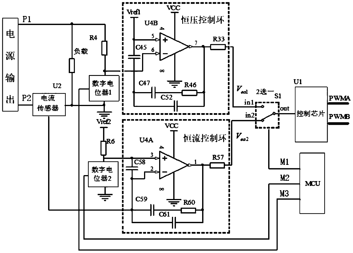
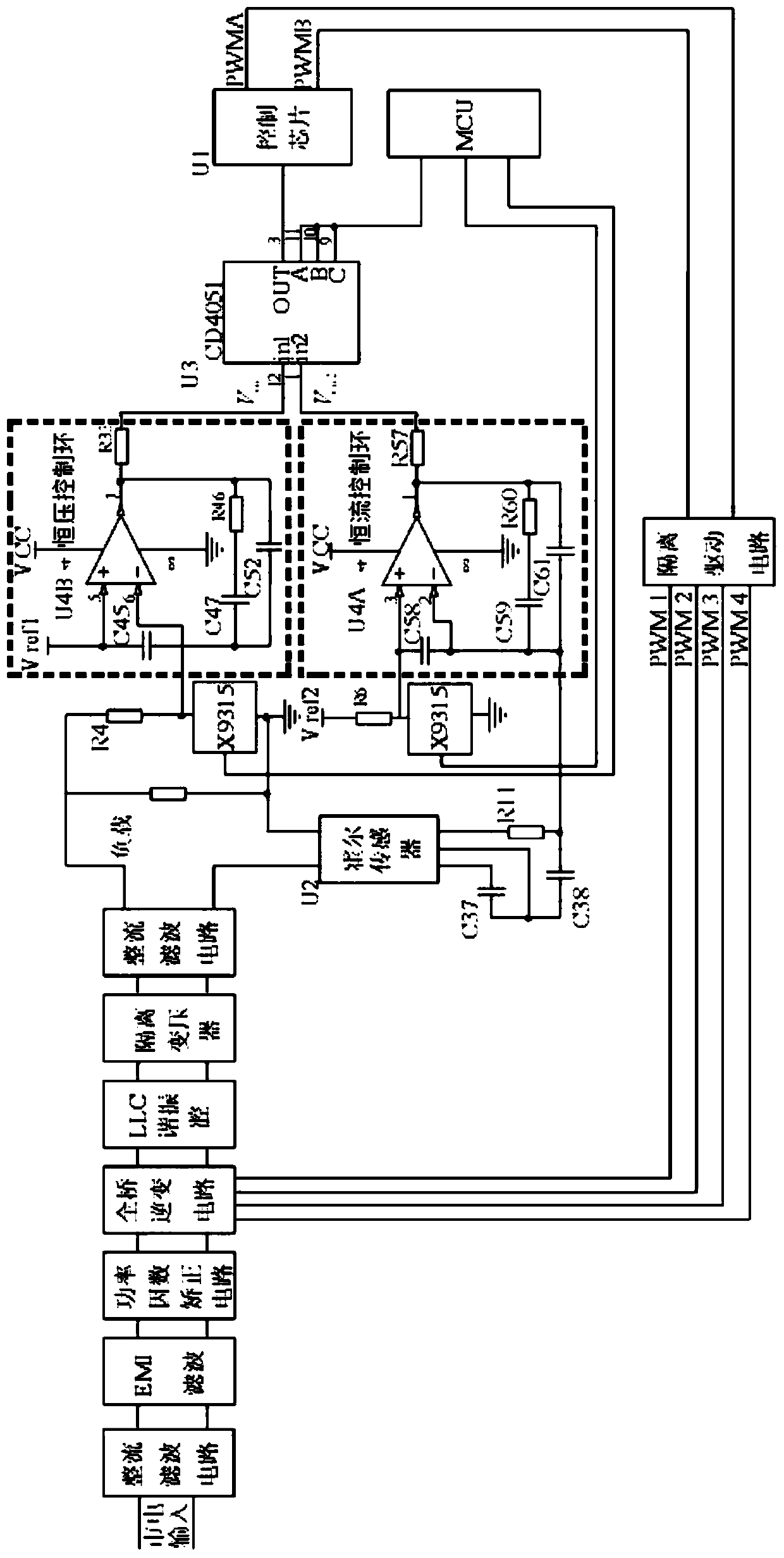
[0047] Such as figure 2 As shown, it is a schematic diagram of a switching power supply composed of a circuit of the present invention. First, the mains input passes through the rectification and filtering circuit to become DC, and after EMI filtering, it is sent to the power factor correction circuit, then through the full-bridge inverter circuit, LLC resonant cavity, and finally through the secondary side of the transformer to rectify and filter the output. In the figure, the full-bridge inverter network is composed of four switching tubes; the LLC resonant cavity is composed of a capacitor and two inductors; the output voltage passes through the resistor R 4 After dividing the voltage with the voltage divider network composed of digital potentiometer 1 (X9315), it is compared with the reference voltage V ref1 The comparison amplifies the error signal V ea1 , V ea1 It is delivered to the in1 end of the CD4051 chip (12 pins of the CD4051); the reference voltage V ref2 Th...


PUM


Abstract

The invention discloses a multi-output mode conversion control circuit of a switching power supply. The control circuit comprises a power output module, a constant voltage control loop circuit, a constant current control loop circuit, an MCU, a control chip, an alternative module, two digital potentiometers and a current sensor. An input voltage is divided by the digital potentiometers; after comparison and amplification by an error amplifier, the MCU controls the alternative module to select the constant voltage control loop circuit or the constant current control loop circuit; and a requiredvoltage value can be set in a constant voltage mode, and a required current value is set in a constant current mode, so that the power supply has constant-voltage and constant-current working modes.The multiple output modes of the power supply can be applied to various power utilization occasions, so that the flexibility and convenience of the power supply in use are improved.

Description

technical field [0001] The invention belongs to the field of power electronic power converters, and in particular relates to a control circuit of a switching power supply. Background technique [0002] Switching power supplies continue to develop towards high frequency, high reliability and multi-working modes. Power supplies that can output multiple voltages and current values ​​have great application value. [0003] At present, the method adopted by the constant voltage power supply is to detect the output voltage of the power supply through the resistor voltage divider network, and calculate it with the voltage value to be output to generate the corresponding driving pulse. The driving pulse is adjusted by the pulse width (the power supply adopts the pulse width modulation mode ( PWM)) or pulse frequency (the power supply adopts pulse frequency modulation (PFM)), to achieve the stability of the output voltage. [0004] The method adopted by the constant current power sup...

Claims


Application Information

Patent Timeline
Patent Type & Authority Applications(China)
IPC IPC(8): H02M3/157
CPCH02M3/157
Inventor 高田程泽羊彦徐龙田雨顺
Owner NORTHWESTERN POLYTECHNICAL UNIV
Why Eureka
Try Eureka