Spinning-effect microelectronics integrated test bed

An integrated test and spin effect technology, which is applied in the direction of measuring devices, instruments, scientific instruments, etc., can solve the problems of detecting pure spin current, measuring without a test bench at the same time, and not being able to test the spin Seebeck effect, so as to achieve saving The effect of measuring time

Active Publication Date: 2019-09-10
NANJING UNIV
View PDF9 Cites 2 Cited by
  • Summary
  • Abstract
  • Description
  • Claims
  • Application Information

AI Technical Summary

Problems solved by technology

Existing measurement schemes cannot accurately detect pure spin current, and the physical mechanisms of various effects are different but organically related, but because there is no corresponding test bench to achieve simultaneous measurement, this leads to the need for multiple samples in multiple measurements This process will bring certain errors, and the efficiency of multiple tests is also very low.
To test the above multiple physical quantities at the same time will face many difficulties. For example, the positions of the waveguide and the test bench carrying the sample are relatively fixed when testing pure spin current, but a test bench is required when measuring spin Hall magnetoresistance The included angle with the external magnetic field is variable; another example is to test the spin Hall magnetoresistance or the pure spin current excited by microwaves, it is necessary to fix the material sample on the insulating plate and connect it to the circuit electrode, but due to the thermal conductivity of the insulating plate low, thus limiting the possibility of applying large temperature gradients in the vertical direction, and cannot be used to test the spin Seebeck effect

Method used


Image

  • Spinning-effect microelectronics integrated test bed
  • Spinning-effect microelectronics integrated test bed
  • Spinning-effect microelectronics integrated test bed

Examples


Embodiment Construction

[0019] The technical solutions of the present invention will be further described below in conjunction with the accompanying drawings and embodiments.

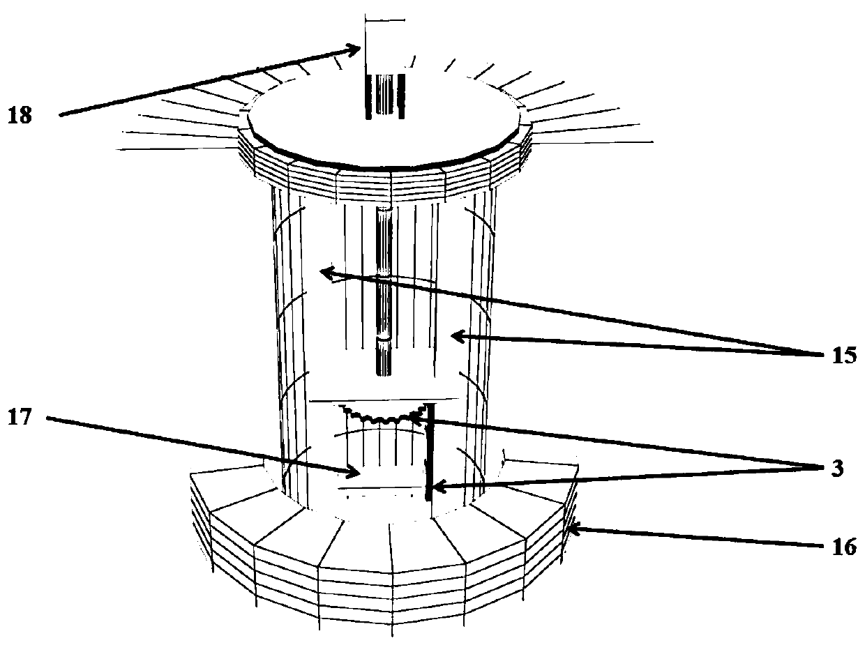
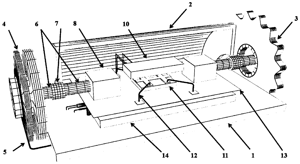
[0020] The spin effect microelectronics integrated test bench of the present invention has an overall structure as figure 1 As shown, it includes a magnet 16 for generating a magnetic field, an outer frame 15, a sample stage 17, and a gear 3 connecting the outer frame and the sample stage. The gear 3 is connected with a motor 18 for driving the sample stage 17 to rotate. The system power supply that powers the test system. Wherein the magnet 16 generates a steady magnetic field, and a superconducting magnet or an electromagnet can also be selected to provide a steady magnetic field. The sample stage 17 is in a steady magnetic field. The test bench also includes sample power supply, measuring instrument (voltmeter and ammeter), temperature controller and microwave signal generator. The above equipment is located outside the ...


PUM


Abstract

The invention discloses a spinning-effect microelectronics integrated test bed. The testing bed comprises a sample bed located in a steady-state magnetic field and rotating around a horizontal shaft;the sample table comprises a measurement unit for measuring a sample electric signal, a microwave unit for forming a microwave field for exciting the sample to produce spinning current, and a heatingunit for establishing temperature gradient on a direction vertical to a sample plane. The test table disclosed by the invention is free from preparing the sample again, multiple spinning-effect related parameters in the same sample are repeatedly measured, the measurement time is saved, and the DC current, the microwave and the temperature gradient can be applied to the sample at the same time, thereby measuring the mutual coupling effect among multiple parameters.

Description

technical field [0001] The invention relates to an integrated test bench for testing the spin correlation effect of a material sample of a microelectronic device, in particular to a microelectronic device for measuring the spin Hall magnetoresistance effect, spin Seebeck and spin current of a material sample Integration test bench. Background technique [0002] With the development of microelectronic devices, the problem of heat dissipation has become a bottleneck in the development of microelectronics. One possible solution to this heat dissipation problem is to exploit the spin of electrons, or spintronics. In spintronics, pure spin current can be used to replace current to transmit information, and there is no Joule heat in the transmission process of spin current, which can greatly reduce the heat dissipation of the device. In order to use the electron spin of the material to design devices, it is necessary to select a suitable electron spin effect material that satisf...

Claims


Application Information

Patent Timeline
Patent Type & Authority Applications(China)
IPC IPC(8): G01N24/00
CPCG01N24/00
Inventor 栾仲智缪冰锋赵辉周礼繁吴镝
Owner NANJING UNIV
Why Eureka
Try Eureka