Terahertz frequency band reflection type polarization conversion device

A polarization conversion and reflective technology, applied in the direction of polarization components, instruments, optical components, etc., can solve the problems of low polarization conversion efficiency, loss, energy loss, etc., and achieve the effects of easy processing, low material cost, and simple graphic structure

Inactive Publication Date: 2019-09-10
ZHEJIANG UNIV
View PDF23 Cites 6 Cited by
  • Summary
  • Abstract
  • Description
  • Claims
  • Application Information

AI Technical Summary

Problems solved by technology

2. Loss, that is, the energy loss caused by the polarization conversion process
The disadvantage of this method is that the large space size is not conducive to the integration of optical systems, the polarization conversion efficiency is low, and the energy loss is large, etc.

Method used


Image

  • Terahertz frequency band reflection type polarization conversion device
  • Terahertz frequency band reflection type polarization conversion device
  • Terahertz frequency band reflection type polarization conversion device

Examples


Embodiment 1

[0038] Example 1: When horizontal linearly polarized waves are incident, at f 1 and f 2 produces vertically linearly polarized waves. Such as Figure 4 As shown in the reflected power spectrum of , when the incident wave is a horizontal linearly polarized wave, at the frequency point f 1 = 0.288THz and f 2 =0.342THz, the power of the horizontal linearly polarized wave in the reflected wave is 0, while the power of the vertically linearly polarized wave is close to 100%. Such as Figure 5 As shown, the polarization conversion rate at the frequency point is f 1 and f 2 The value at is close to 100%, which indicates that the energy of the incident wave undergoes almost complete linear polarization conversion at these two frequency points. by f 1 and f 2 From the electric field simulation at , it can be found that the resonance modes at the two frequency points are different. at lower frequencies f 1 At , the direction of the electric field in the two rectangular holes ...

Embodiment 2

[0039] Example 2: When horizontal linearly polarized waves are incident, at f 3 and f 6 produces right-handed circularly polarized waves. Such as Figure 6 As shown, at the frequency point f 3 = 0.283THz and f 6 =0.344THz, the reflectivity of the horizontally polarized wave and the vertically polarized wave in the reflected wave is both 50%, so the electric field strength of the two is equal. also because Figure 7 middle f 3 and f 6 The phase difference between the corresponding vertical electric field and the horizontal electric field is -90 degrees, so at f 3 and f 6 The reflected wave at is a right-handed circularly polarized wave.

Embodiment 3

[0040] Example 3: When horizontal linearly polarized waves are incident, at f 4 and f 5 produces a left-handed circularly polarized wave. Such as Figure 6 As shown, at the frequency point f 4 = 0.296THz and f 5 =0.340THz, the reflectivity of the horizontally polarized wave and the vertically polarized wave in the reflected wave is both 50%, so the electric field strengths of the two are equal. also because Figure 7 middle f 4 and f 5 The phase difference between the corresponding vertical electric field and the horizontal electric field is 90 degrees, so at f 4 and f 5 The reflected wave is a left-handed circularly polarized wave.


PUM


Abstract

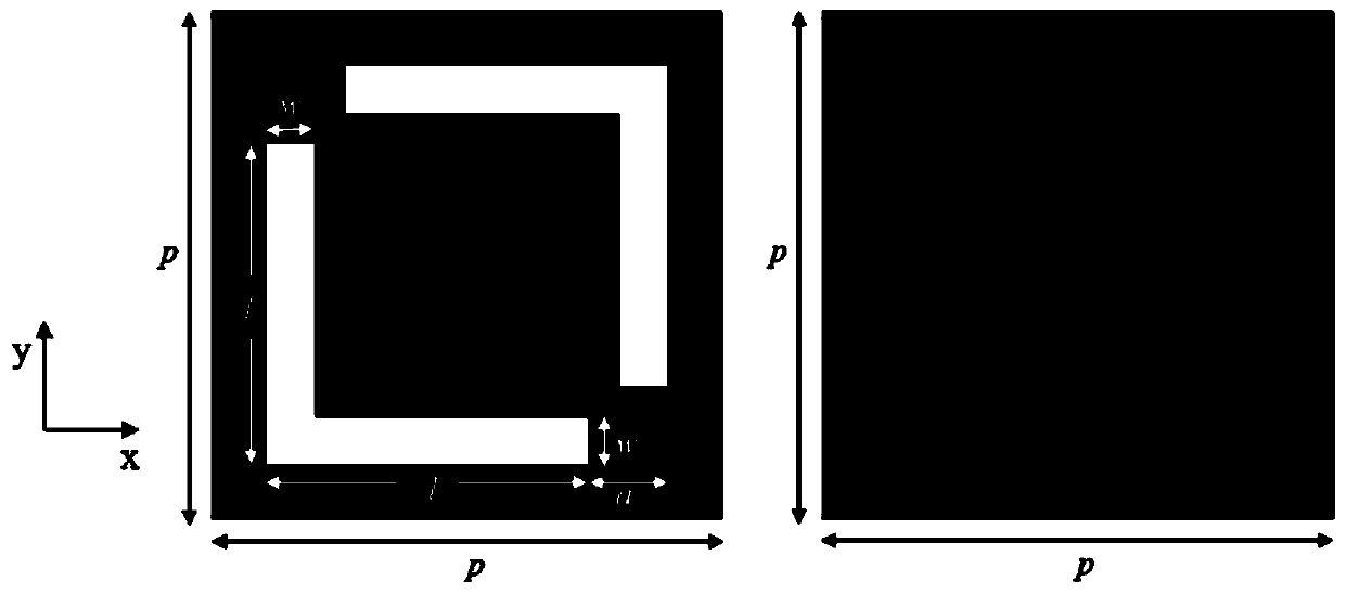
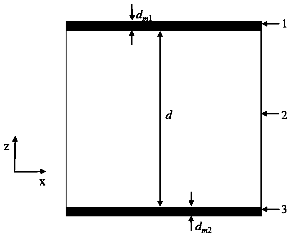
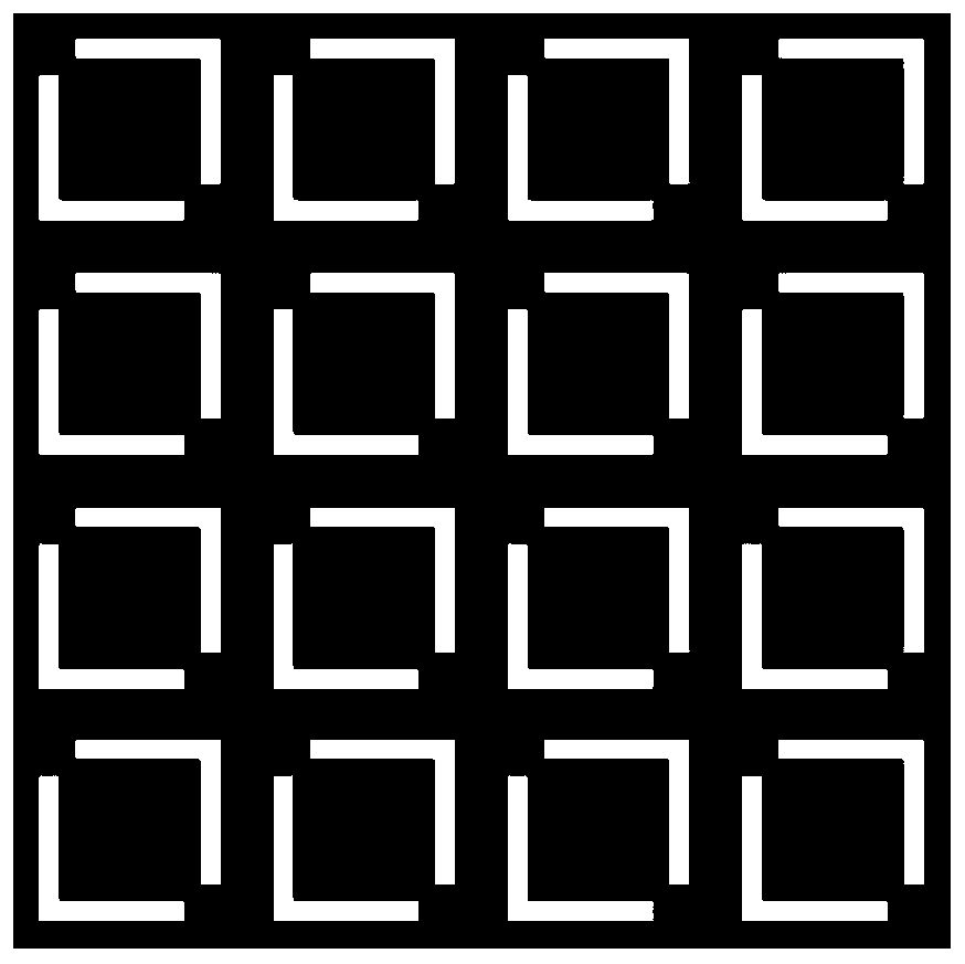
The invention discloses a terahertz frequency band reflection type polarization conversion device. The device comprises at least one periodic structure unit. The periodic structure unit consists of athree-layer structure of an upper metal layer, a dielectric layer and a lower metal layer, the upper metal layer is a periodic sub-wavelength array hole structure, and the middle layer is a dielectriclayer; the upper metal layer forms a periodic sub-wavelength array structure with symmetrical double L-shaped grooves by chemical etching, the double L-shaped grooves are arranged in the middle of the upper metal layer and are oppositely separated, and the double L-shaped grooves are symmetrically arranged on the diagonal line of the upper metal layer; and each L-shaped groove is formed by vertically connecting two strip-shaped through grooves in an L shape, and the two sides of the L shape are equal in length and width. The terahertz frequency band reflection type polarization conversion device realizes the reflection type linear polarization and circular polarization conversion of the terahertz frequency band, and has important application in terahertz radar, imaging and communication systems.

Description

technical field [0001] The invention relates to the field of terahertz wave polarization conversion and the field of metamaterial surfaces, in particular to the realization of reflective polarization conversion of terahertz waves by utilizing surface plasmon resonance excited by terahertz waves on metasurfaces. Background technique [0002] Terahertz radiation is a frequency band with unique electromagnetic properties in the electromagnetic spectrum, located between microwave and infrared radiation. Due to the particularity of the frequency band, the terahertz band shows many irreplaceable advantages and excellent application value. For example, terahertz waves have excellent penetrability to many dielectric materials (such as plastics, foams, ceramics, etc.), and can be used for safety inspection and quality inspection in special occasions; lower photon energy has higher safety performance for biological Detection; with high spectral resolution capability, it can be used f...

Claims


Application Information

Patent Timeline
Patent Type & Authority Applications(China)
IPC IPC(8): G02B5/00G02B5/30
CPCG02B5/008G02B5/30
Inventor 徐川善杨冬晓
Owner ZHEJIANG UNIV
Why Eureka
Try Eureka